

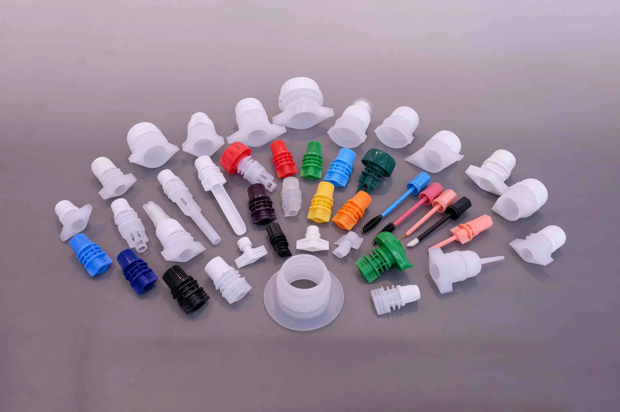
A pouch closure that leaks, rattles, or refuses to twist costs far more to fix than to prevent, and the cheapest place to catch all three is before anyone cuts steel. A 3D-printed closure prototype is a functional sample of a spout cap for stand-up pouches, or of any other pouch closure, printed in plastic so the interface can be handled and tested while the only thing committed to a supplier is a drawing. What you are buying is not a product. It is information.
That distinction matters more for pouches than for the snap-fit joints written up everywhere else. A closure for a stand-up pouch (a doypack, in most export markets) is a sealed, food-contact, repeatedly opened junction between three separate things: your film, your filling line, and your product. A printed prototype tells you the truth about one of those at a time, and knowing which one is the actual skill.
What a 3D-printed closure prototype can and cannot prove
A 3D-printed closure prototype is a short-run functional sample of a pouch closure, produced by additive manufacturing so that interface geometry, closure function and handling can be evaluated before steel injection tooling is ordered. It is a test article, not a production part.
Getting that boundary wrong in either direction is expensive. Assume the printed part proves everything and you order tooling on a partly unanswered brief. Assume it proves nothing and you skip the one test that would have shown the cap sits 0.4 mm off the seal jaw.
These process families are now standardised, and the vocabulary is worth keeping straight when you brief a supplier: material extrusion (what most people mean by FDM), vat photopolymerization (SLA and DLP), and powder bed fusion (SLS and MJF) are three of the seven categories defined in ISO/ASTM 52900.
Question | Printed prototype | How to close the gap |
|---|---|---|
Does the closure fit my film and neck? | Settles it | Measure the weld zone, not the drawing |
Does it open, close and seal by feel? | Settles it, partly | Wear-test the hinge in production resin |
Will the weld hold on my line? | Geometry only | Seal trial with your film and your jaws |
Will it survive the product? | Fill trial only | Chemical compatibility on production resin |
Is it food-contact compliant? | No | Test the production part, per Regulation (EC) 1935/2004 |
Why test a printed closure before you commit to steel tooling
Tooling quotations are not catalogue prices. A pouch closure mold is priced from its geometry: the number of cavities, the undercuts and side actions your closure needs, the steel, the finish on the sealing face, and how many of those details must survive a 60-day build. Change one dimension of a snap bead after the quote and the quote changes with it. This is why a serious molder will not put a number on a mold until the 3D drawing is locked, and it is the single strongest argument for producing a printed sample from that same locked drawing first: the drawing stops moving for the price of a prototype instead of the price of a tool.
The arithmetic is not close. A mold is a fixed cost paid once, sitting in front of everything else, and the mistakes it locks in are the ones that surface late — at the filling line, in a leak test, or in a customer complaint. A printed closure costs a small fraction of that and answers the interface questions long before a mold would be ready. For a broader walk-through of how the design, tooling, trial and production stages connect, see from sketch to mass production; for how the tooling number itself is built up and how many sampling rounds to budget, see spout cap tooling cost and sampling rounds.
The most expensive error is not a prototype that fails. It is a mold that succeeds at making the wrong closure — one that closes perfectly in a picture and fights your capping head on a real line.
Iteration is cheap while the part is printed. After steel, every change is a tool modification.
Five things you can test on a 3D-printed pouch closure
A printed closure is worth the run only if you test it on purpose. These five checks take an afternoon with a caliper, a torque gauge, a few pouches of your own film, and the actual product.
1. Neck and pouch interface fitment
This is where a printed part outperforms every drawing. Check the spout fitment against the weld zone on your pouch film: is the weld flange wide enough for the seal jaws you actually run, does it land where the pouch corner has film to spare, does the spout base sit clear of the top seam? Fit the closure to your neck finish and confirm thread engagement, then check the seated height against your headspace. For a doypack spout cap, the dimension that matters most is the spout inner diameter against your fill — a thick puree, a 10 mm sauce and a 1.2 mm cosmetic essence are three different closures, and holding that bore to a tight tolerance is what keeps the fill rate predictable. On this site the published tolerance on inner diameter is ±0.1 mm of nominal. That band belongs to the molded part, not to the print — the tolerance a printed prototype can hold is several times looser than that — so treat ±0.1 mm as the target a custom spout cap project has to reach in production, and use the printed sample to check that the design leaves room to reach it.
2. Closure function, feel and open/close cycles
Twist it. Flip it. Do it fifty times and hand it to someone who has never seen the design. This is the check that no 3D model and no render can perform, and printed prototypes are uniquely good at it, because the geometry is real even when the resin is not.
What you can settle: thread lead and engagement, whether the cap cross-threads when it is started off-axis, whether a flip-top lid clears the spout when open, where a tamper-evident band has to sit to be gripped, and whether the closure reads as "open" or "closed" to a hand. What you cannot settle: hinge life. A printed living hinge on a flip-top cap usually fails at the layer lines long before a molded one would, so use it to prove the kinematics and the open angle, and leave cycle life to production resin. The general closure-design caution applies here too — the snap features that give a cap its click are annular or cantilever geometries, and their root radius and the material behind them decide whether they hold or crack.
3. Seal geometry against your film and fill
Printed closures are the right tool for arguing about seal geometry, and the wrong tool for proving a seal. Build the prototype so the sealing face, the flange width and the plug or spigot detail are dimensionally true, then check them against the film you will actually run — a mono-material PE laminate behaves differently from a foil-bearing structure, and a closure engineered to weld to recyclable PE at a low sealing window has different geometry from one that relies on a hot jaw.
Two limits are worth stating plainly. First, a printed sealing surface carries layer ridges, and a ridge is a leak path; the geometry can be validated on the print, the weld cannot. Second, the seal belongs to a temperature window on your machine, not to the part in your hand — the pouch spout sealing temperatures that work for a given closure and film have to be dialled in on your sealer. For more on that window, see pouch spout sealing temperatures.
4. Handling behaviour on your filling line
The filling line is where closures fail in ways nobody predicts on paper. A printed prototype lets you rehearse the physical interface before tooling: does the spout present in the right orientation for your feeder, does it sit flat enough for vacuum pick-up, does a lightweight printed cap behave as a lens or slide on the capper, and does the assembled pouch survive the drop from the line onto the conveyor without the cap popping? None of this requires production resin — it requires the right silhouette, and the printed part has it.
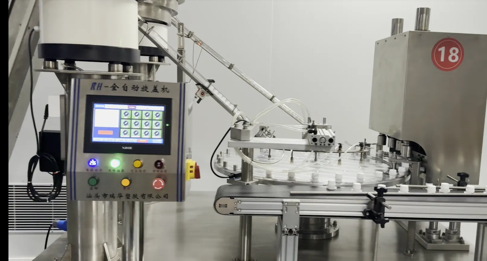
The capping interface in the factory: spout caps are fed and oriented on a rotary capping machine — the machine interface a printed prototype lets you rehearse before tooling exists.
5. Contents and chemical exposure
Fill the assembled prototype with the real product and leave it. An acid sauce, a detergent, an alcohol-based sanitiser and a fragrance oil will all find different things to attack: the closure body, the thread, the liner seat, or the film at the weld. A printed part is chemically the wrong plastic for a final verdict, but it is a good early screen for gross failures — swelling, staining, stress whitening, a lid that will no longer snap. Treat anything this trial flags as a design question, and take anything it clears as provisional until it is repeated on production resin and a production part.
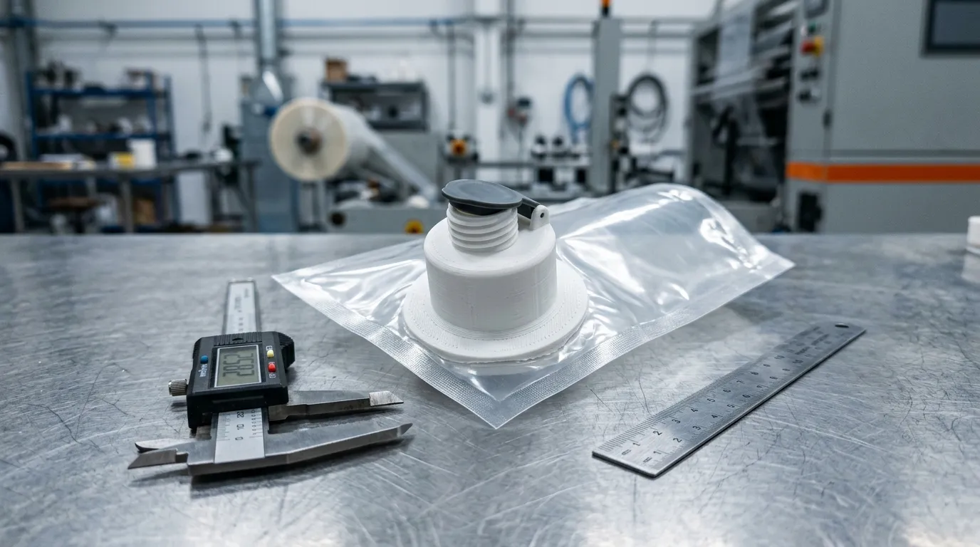
Illustrative render, not a photograph of a client part. The argument it stands for: a printed closure is a geometry proxy — the layer ridges a print leaves on a sealing face are exactly why a weld cannot be validated on one.
Choosing a print process and material for closure prototypes
Closures need stiffness, thread strength and a hinge or snap bead that survives handling, which narrows the sensible choices. The table below is about what each process can tell you at a closure interface, not about which process is better.
Process | Good for closures | Where it misleads |
|---|---|---|
Material extrusion (FDM) | Fast silhouette checks, film fitment, drop tests | Layer ridges on sealing faces; weak Z-direction |
Vat photopolymerization (SLA/DLP) | Smooth surfaces, thread form, fine lids and caps | Standard resins are brittle; poor for repeated opening |
Powder bed fusion (SLS, MJF) | Functional snap beads, hinges, torque feel in nylon | Porous surface; needs sealing before any liquid trial |
Material jetting (PolyJet-style resin) | Appearance, fine detail, presentation models | Resin, not nylon; too brittle for a functional closure |
For a closure you intend to open and close repeatedly, powder bed fusion in nylon is the usual first pick because it is tough rather than stiff, and the layer direction matters less. FDM is excellent for film and flange fitment and for weight and drop behaviour; it is the worst choice for anything that has to seal. Standard SLA resin produces beautiful thread forms and cracks if you treat it like a real cap.
One capability is worth asking about if your closure has a living hinge or a two-part action. Powder bed fusion can build a hinge or a latch already assembled in a single printed piece — print-in-place — so the open-close kinematics can be evaluated as one part before tooling, without a second component to assemble.
Three process details decide whether your test is meaningful. Orientation: printed parts are anisotropic, so a cap printed with layer lines running across a thread or a snap bead will fail along those lines for reasons that have nothing to do with the design — orient the part the way the loads arrive, and print both ways if the answer matters. Tolerance: there is no universal figure, and the achievable band depends on the process, which is why published design guidance for printed parts is quoted per process rather than as one number — printed tolerance is typically looser than most closure interfaces can live with, so design the prototype so the critical dimension becomes measurable rather than assumed. Wall thickness and corners: uniform walls, generous fillets at the root of any snap feature, and no sharp internal corners, because the corners are where crack initiation starts in every process, printed or molded.
Additive manufacturing is not a single thing, and the reliability of a printed part is process-specific; NIST's additive manufacturing programme is a reasonable place to read past the marketing claims that printed parts behave like molded ones.
What a printed prototype cannot decide — the five answers that still need steel
The honest half of this article. A printed closure is a dimensional proxy, and five decisions belong to the mold and the resin.
Shrinkage. Polypropylene and polyethylene shrink as they cool, and the same nominal geometry produces different final dimensions in different resins. How much, and in which direction, belongs to the mold and the resin; a printed part does not shrink the way a molded one does, so it cannot predict the finished cap. It can confirm that a design has room for the correction.
Wall uniformity, sink and weld lines. Injection molding fills a cavity at pressure; printed parts are built. Sink marks behind a thick boss, weld lines where two flow fronts meet, and short shots at the end of a thin section are all invisible in a print and visible on a real part.
Function that lives in the resin. Living-hinge life, the snap force of a tamper-evident band, and the opening force of a child-resistant closure are material and process outcomes, not shape outcomes. A printed hinge proves the kinematics; the life of the hinge is proved by molded resin.
Cost per part and cycle time. These belong to the cavity count and the tool, and no prototype can answer them.
Compliance. A printed closure is not a food-contact part. Printed surfaces are porous and retain material, and post-processing changes what can migrate; compliance is decided on the production material and the production part against the applicable rules — for plastic food-contact articles in the EU, that framework includes Regulation (EU) No 10/2011. Never let a clean prototype stand in for that evaluation.
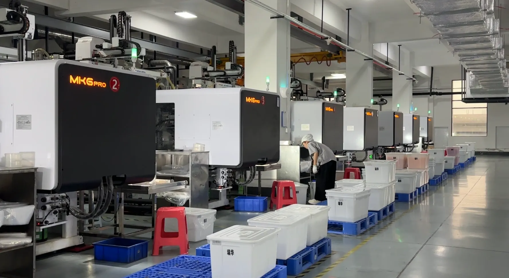
Between a printed prototype and a production mold there is a third option worth knowing by name. Prototype tooling — also sold as soft tooling, bridge tooling or a short-run prototype injection mold — gets parts from an aluminium or lower-grade cavity in smaller numbers, which answers shrinkage, wall behaviour and one-piece function questions without the cost or the lead time of a hardened production tool. If your uncertainty is in the material rather than the geometry, that is the step to price. And if nothing about the closure is actually new — the film, the fill and the neck are all known, and the cap you want already exists in someone's stock — skip the prototype altogether: it would add a step and answer nothing.
How we run the prototype step before a pouch closure mold
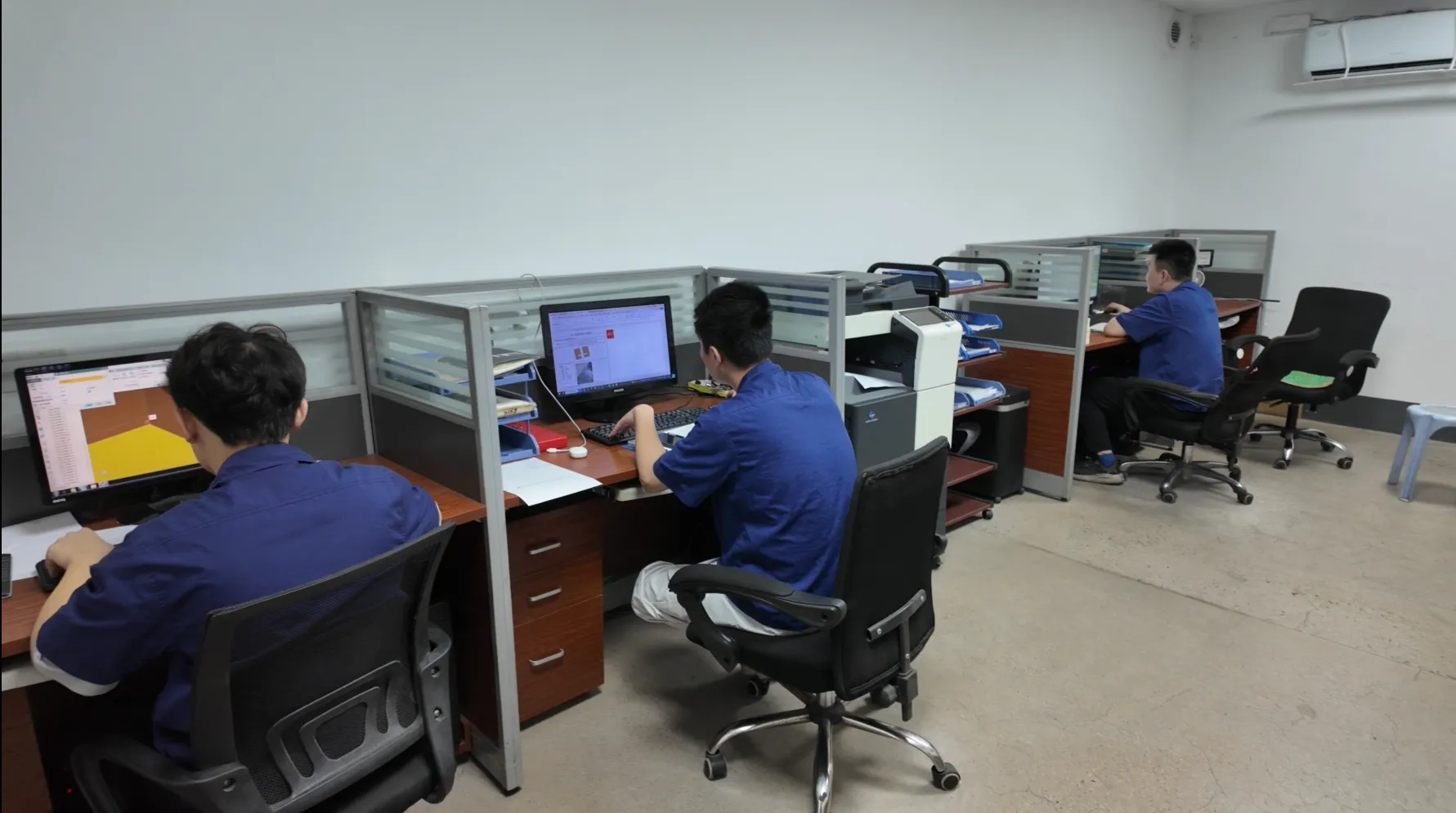
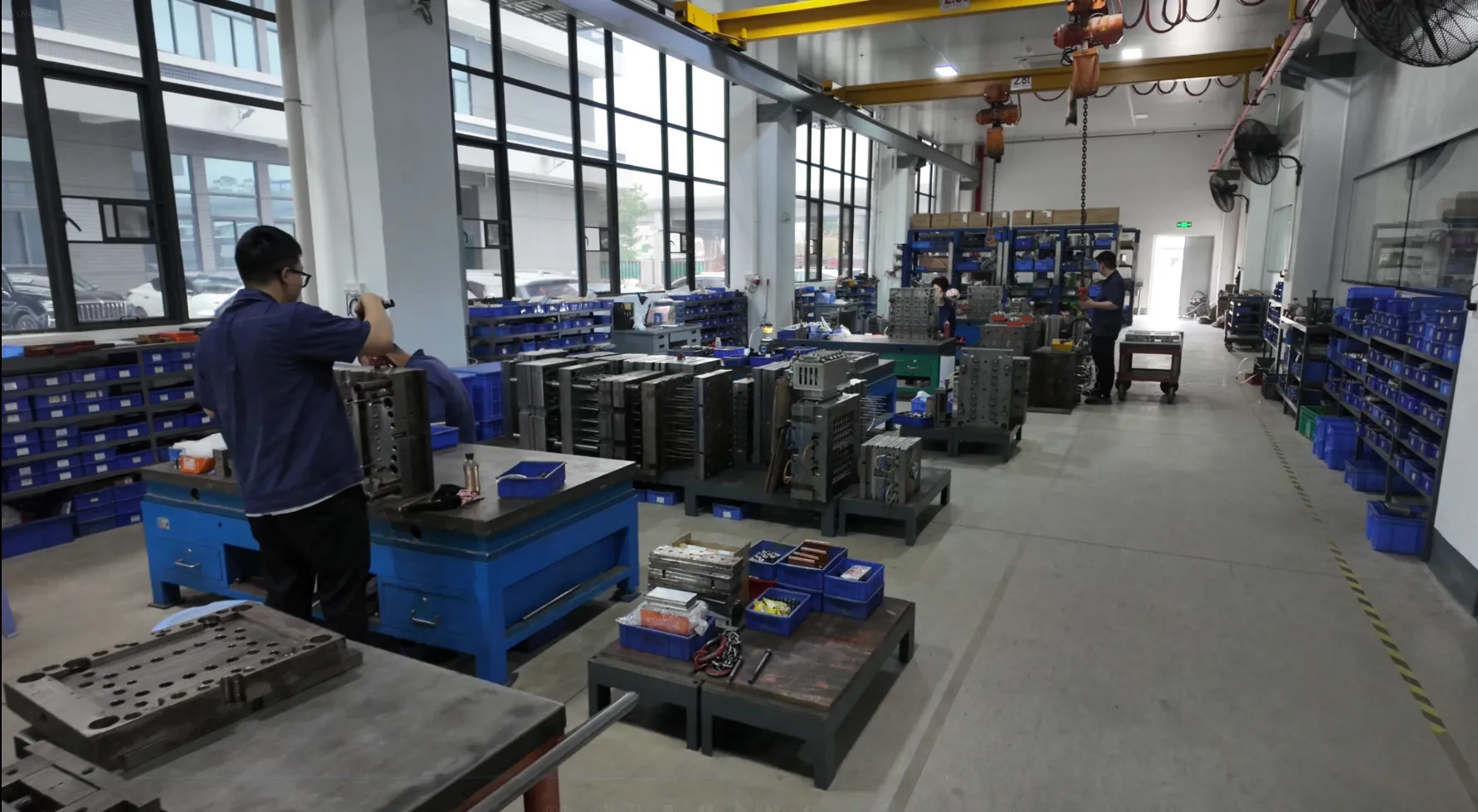
At Shantou Ruihua Plastic the closure prototype sits inside a longer tooling habit rather than beside it. Mold-making here starts with an in-house department whose heritage goes back to 1999, and the company holds 38 patents across invention, utility and design registrations; 3D mold printing is used inside that department to iterate on tooling and on part design before metal is cut. For you as a buyer, the practical sequence is short and worth asking any supplier to repeat back to you.
The 3D drawing is locked first, and only then is a mold quoted — the price depends on the geometry, so quoting before the drawing is guesswork. Once that drawing exists, a printed prototype can be produced for handling and fit testing. Mold production then runs on a cycle of roughly 60 days, which is the window in which a printed sample earns its keep. Around all of it sit the capabilities that make the transition to production boring: a 70,000 m²+ facility and 130+ sets of production equipment, a dust-free injection workshop, in-house laboratories and a test room, and machine-vision full inspection available on request rather than as a default.
Two closure ranges sit either side of the tooling decision. If a stock cap already fits your film and your fill, custom tooling is unnecessary. If nothing stock fits, the same drawing discipline applies from a different direction, and the hub for that work is custom tooling for pouch closures.
A prototype test plan you can send your supplier
Print this, fill it in, and attach it to the brief. A prototype that arrives without a test plan gets handled for a week and then sits in a drawer.
Check | Method | Pass criterion | Record |
|---|---|---|---|
Film fitment | Lay the part on your film at the weld position | Clear of seams, inside jaw footprint | Photograph with film in place |
Neck and thread | Hand-thread onto the matching neck | Full engagement, no cross-threading | Turns to seat; seated height |
Seal geometry | Dry-fit the sealing face to the film | No rock, no gap over the seat | Feeler gauge result |
Open/close feel | 50 open-close cycles by two people | Consistent action, no loosening | Notes on force and noise |
Line handling | Run pouches past your feeder and capper | Presents, picks and caps without jams | Reject rate on a short run |
Product exposure | Fill and hold with the real product | No swelling, staining or stress whitening | Temperature and days held |
If you would rather work through the same questions as a guided sequence, the sample and validation planner walks from contents and film to the sample checks that matter for those choices, and produces a brief you can hand over.
Questions to put in writing before you approve tooling
Six questions, in order, and ask for written answers. Whether the replies come from us or from another supplier, the answers are what tells you whether the prototype step is being run properly.
- What exactly is quoted, and what has to be locked before the price is fixed?
- Which dimensions in the prototype are true to the production part, and which are placeholders?
- What will be tested on the trial-shot samples, and to what tolerance?
- How many sampling rounds are included before the tool is considered accepted?
- What happens to the tooling if the closure has to change after the first shots?
- Which documents do you supply to support a food-contact evaluation of the production part?
A printed closure has done its job the moment it turns a disagreement into a measurement, and the cheapest version of this article is the one you read before writing the mold purchase order. If the closure you are prototyping is a pouch spout, it is worth checking first whether a stock spout cap range already covers the film, the fill and the diameter you need; if it does not, request a printed sample and a quote against your drawing and we will tell you what the prototype can settle.


