


Question 14 of a retailer's packaging questionnaire asks you to state the seal strength of your spouted pouch. Answer with a number and you have not answered the question underneath it, which is whether the pack leaks. Seal strength vs seal integrity is a distinction between a force and an absence: strength is how much load the bond carries before it separates, integrity is whether there is any path through the closed pack for liquid, gas or microbes. One is reported in newtons per 15 mm or pounds-force per inch. The other is reported as a leak rate or a pass/fail against a limit you chose.
Treating them as one number is how a pouch with a perfectly respectable 12 N/15 mm fin seal still ships with a channel in its flange weld. This page separates the two measurements, maps them onto the three seals a stand-up pouch or doypack actually has, and ends with the five lines that belong in a specification. It sits inside the Choosing & Running Spout Caps series, where "spout cap" always means the closure on a stand-up pouch, never a gas-can spout.
Seal Strength vs Seal Integrity: Two Measurements, Two Failure Modes
Strength and integrity fail in different directions, which is why a result from one cannot stand in for the other.
A strong seal can leak. Weld a flange at the right temperature and pressure over a film area with a speck of sauce in it, and the bond that does form measures well — the peel force is carried by the fused material either side of the contamination. The channel left by that speck runs along the seal and never crosses the peel path, so the peel test never loads it. The pack passes strength and weeps in a carton three weeks later.
A sound seal can be weak. A continuous weld with no contamination and no pinhole can measure below a nominal target because the resin pair is soft, the dwell was short, or the film's seal layer is thin. Nothing leaks on day one. Then the pack takes a drop in transit, the bond creeps, and the failure appears as a split at the flange edge — logged by the customer as a leak, caused by a strength shortfall.
Seal strength | Seal integrity | |
|---|---|---|
The question it answers | how much force does the bond carry before it separates | is there a path through the closed pack |
What is measured | force per unit width of seal, plus a failure mode | presence of a leak, or a leak rate |
Specimen | a cut strip of sealed film, or the fitment weld on a sacrificial pouch | the whole sealed pack, usually filled |
The result looks like | a number: N/15 mm, lbf/in, and peak or mean | pass/fail against a criterion, or a rate |
Typical method | ASTM F88 peel | dye penetration, bubble emission, vacuum decay, burst |
Blind spot | a channel that never crosses the peel path | how much load the bond can carry |
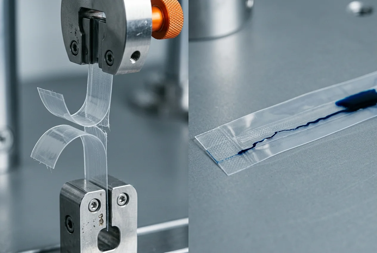
Two different questions, two different specimens. The strip on the left reports a force; the pouch edge on the right reports whether product can travel.
What an ASTM F88 Seal Strength Test Actually Tells You
ASTM F88, the standard test method for seal strength of flexible barrier materials, supports a sealed specimen between grips, pulls it apart at a controlled angle, and records force against extension. From that trace you get two usable numbers — peak force, the highest point reached, and mean force, the average over a defined peel length — plus the failure mode.
Units are the first trap. Metric packaging practice reports N/15 mm of seal width; US practice reports lbf/in. They are not interchangeable at a glance: 1 lbf/in is about 2.6 N/15 mm, and 10 N/15 mm is about 3.8 lbf/in. A supplier quoting "1.2" and a customer expecting "12" may be describing the same seal in different units, or may be an order of magnitude apart.
Four conditions have to travel with the number, because each one moves it:
- Specimen width. The force scales with the width you cut. A 15 mm strip and a 25.4 mm strip from the same seal are not comparable until normalized.
- Peel geometry. A 180° peel, a T-peel and a supported peel with a backing plate load the seal differently. Free-tail and backed specimens from the same lot routinely differ.
- Crosshead speed. Faster pulls read higher on stiff laminates. If the speed is not written down, the number is not reproducible.
- Failure mode. This is the one reports leave out and the one that decides whether the number means anything.
Failure mode comes in three useful varieties. Adhesive failure peels cleanly at the interface and gives a flat force plateau — the seal is weaker than the materials, so the number genuinely describes the seal. Cohesive or delamination failure tears inside the film or the seal layer, and the force climbs as the structure fails rather than the bond. Film tear means the film broke before the seal did: the seal is stronger than the material around it. That is usually good news for the pack and bad news for the specification, because the number you recorded is a property of the film, not the seal, and raising the sealing temperature further will not raise it.
There is a companion standard for the other half of the job. ASTM F2029 defines how to make laboratory heat seals so that sealing conditions can be compared at all. A strength number without the F2029 conditions that produced it is an anecdote. And to keep one adjacent term out of the conversation: hot tack is the strength of a seal while it is still molten, measured seconds after the jaw opens. It governs how a form-fill-seal line runs at speed. It is not a shelf-life property and not a substitute for either metric here.
What a Seal Integrity Test Proves — and Where It Stops
Integrity testing starts from a different premise: a leak is a path, not a property of the pack. On a spouted pouch the path begins in one of four places — the cap-to-spout closure, the flange weld, the film body and back seal, or the fitment body itself, where a hairline crack at the shoulder follows an over-torqued cap.
The methods divide by what they can see. Dye penetration (ASTM F3039 for nonporous packaging) draws a colored solution into a leak and leaves a stain you can map. Note the standard number carefully: ASTM F1929 is the dye method for porous medical packaging, and it is the wrong document to write into a laminate pouch specification, however often its number gets quoted. Bubble emission (ASTM D3078) immerses the pack and counts bubbles.
Vacuum decay (ASTM F2338) is non-destructive and instrumented, which is what makes routine auditing affordable. Internal pressurization (ASTM F1140) pushes the pack until it fails and reports the pressure, which is a burst resistance rather than a leak finder.
Every one of those tests has a detection limit, and a passed test only proves the absence of leaks above that limit. A method that finds nothing at 100 µm has not shown the pack is airtight; it has shown the pack has no leak larger than roughly 100 µm. If your specification does not name the limit, your supplier and your auditor are entitled to assume different ones.
The choice between methods is mostly a choice about frequency, which is a choice about cost. A destructive test consumes the pack, so it can only be sampled — a few packs per batch, per shift. A non-destructive test can go on every pack or on an audit frequency, but needs an instrument and a fixture. Cheap-per-test and cheap-per-year are different numbers, and the second one is the one your plant manager will ask about. The method menu, the sampling logic and the acceptance criteria are worked through in choosing a non-sterile pouch leak test; what matters here is that integrity is the metric that answers the leak question, and strength is not.
One framing note, because it explains why this page has to exist. Sterile medical packaging arrives with the framework pre-written — ISO 11607 for the sterile barrier, and FDA guidance on container and closure system integrity testing treating integrity testing as a documented alternative to sterility testing. A sauce, detergent or shampoo pouch has no equivalent. There is no mandated method, sample size or acceptance criterion, which means the specification you write is the standard. Nothing on page one of this search says that out loud.
A Spouted Pouch Has Three Seals, Not One
Every page ranking for this query treats "the seal" as a single thing. On a spouted pouch it is three, and they are made by different processes, on different equipment, at different moments.
- The back and fin seals, film to film, made by the pouch maker's sealing bars before the pouch ever reaches you.
- The flange weld, molded spout fitment to the film's seal layer, made on the filling and sealing line.
- The cap-to-spout closure, a threaded or push-pull joint that is not welded at all.
Joint | What governs it | How it is usually checked | How it fails |
|---|---|---|---|
Back / fin seal (film to film) | strength and integrity both | F88 strip peel for strength; whole-pack dye, bubble or vacuum decay for integrity | cold seal, wrinkle, product in the seal, seal bar wear |
Flange weld (fitment to film) | integrity first, plus weld-face width | whole-pack integrity test on a filled pack; strength on a sacrificial pouch | channel from contamination, uneven jaw pressure, resin mismatch |
Cap-to-spout closure | integrity, plus application torque | vacuum decay or dye on the assembled pack; torque check at the capper | cross-thread, insufficient compression land, valve stuck open |
Fitment body and shoulder | integrity only | the same whole-pack tests | hairline crack from over-torque or an angled cap |

One pack, three joints, three different processes. The cap is threaded on, the flange is welded by the line, the side seal was made by the pouch maker weeks earlier.
The practical consequence is blunt. A single "seal strength: 12 N/15 mm" line in a questionnaire is a statement about whichever joint somebody happened to test, with no way for the reader to know which. Three joints, one number, and two of the joints — the ones that actually leak on a spouted pack — are not described at all. Failures that reach this point after filling are worked back to their joint in diagnosing a spout that leaks after filling.
Why the Flange Weld Breaks the Standard Playbook
The spout flange weld is where the two metrics stop being interchangeable and start being awkward.
Geometry is the reason. A fin seal is a flat band you can cut into a strip, clamp in grips and peel. A flange weld is a ring a few millimeters wide, running around a circular or oval fitment, joining a molded part of significant wall thickness to a laminate a fraction of a millimeter thick. Cut a strip across it and the specimen is mostly fitment; pull it and the film tears at the flange edge before the weld lets go. The test then measures the film's tear resistance, at the stress concentration the flange created, and reports it as a seal strength.
Image the joint in section, and the second difficulty appears: the two materials do not heat at the same rate. The molded fitment has far more thermal mass than the film, so the jaw has to deliver enough energy to bring the weld face up to temperature without cooking the film beside it. That is what the weld face — the flat annulus on the underside of the flange — exists to manage. Its width is the number that decides how much fused area you get for the pressure your jaw can apply.

A sacrificial pouch, cut open and peeled: the fused ring is the only material the two parts share. Everything around it is film that an F88 strip would tear first.
So the flange weld gets a different instrument and a different data set:
- Strength is measured on a sacrificial pouch. Weld a pouch, cut it open, and peel the fitment away from the film to read the force it takes. That number is a total force for that weld, not a force per unit width, and it is not comparable to a fin-seal N/15 mm figure. Put it in its own column or leave it out.
- Integrity is the workhorse. A filled, sealed pack either holds vacuum or it does not, and that answer covers the whole ring at once. This is the metric that belongs in the acceptance criterion.
- Weld-face width and placement are dimensional, checked on the part and on a section, not on a pull tester.
Resin choice sets the floor under all three. A spout has to fuse to whatever seal layer the film carries, and our low-temperature sealing grades are engineered to weld at 110–130 °C, which is what lets a spout join a mono-PE structure without the film's own structure collapsing at the jaw. A lower welding window is not only a recyclability feature — it widens the overlap between the film's window and the fitment's, which is the overlap your line actually runs in. Carrying a sealing temperature across from a different film structure without re-checking that overlap is one of the reliable ways to create a channel that passes a peel test; the window logic is set out in spout cap sealing temperature.
One more geometry conflict worth naming: the flange occupies film that the top seal used to own. A wide flange and a narrow top seal leave less overlap than the pouch's own seal specification assumed, and the resulting weak spot is at the pouch top, not at the weld. That is a pouch-and-fitment layout question, and it is decided before the first pack is filled.
The One-Pound-Per-Inch Rule Is Not a Specification
Somewhere in most packaging protocols there is a line reading "minimum seal strength: 1 lb/in" — protocols routinely drop the f, and the figure means pounds-force per inch — and almost nobody who wrote it can say where it came from. The trail leads back to EN 868, the European series for sterile medical packaging — or so DDL's engineers calculate. DDL, a packaging test laboratory, puts the point plainly in its write-up on the one-pound minimum: most protocols it sees carry the requirement, and the number should instead come out of process validation. Packaging Digest traced the same figure to material suppliers guaranteeing a 1 lbf peak for peelable seals — a supplier's capability statement, not a requirement on your pack.
Four things are wrong with using it as a universal criterion:
- It is not tied to the pack. A 40 g sachet and a 5 kg pet-food pouch do not have the same load case, and one number cannot serve both.
- It measures a flat seal, not your joint. On a spouted pouch the joint that matters is a ring around a molded part, and the strip test that produced the one-pound figure does not describe it.
- Peelability is the wrong goal here. A one-pound peelable lid is designed to open. A flange weld is designed never to open. Strength for a flange weld is a process-drift indicator, and treating it as a pass mark confuses a lid requirement with a body requirement.
- It says nothing about leaks. A pack can hold 3 lbf/in and still weep through a channel beside the weld.
What replaces it is your own data, and the shape of the work is not exotic. Make seals across the low, nominal and high end of your temperature, pressure and dwell window, on your film and your fitment, on your line. Measure strength and integrity at each point. The leak-free region of that matrix is your process window; the strength values inside it are your baseline. Set the acceptance criterion at the bottom of the leak-free region with a margin your process control can actually hold — then the number is defensible, because it was derived from the packs you ship rather than borrowed from a standard written for sterile devices.
The same logic applies to the integrity side. Name the method, name the detection limit, name the sample size and the frequency, and name the record. "Leak tested" is not a criterion; "no leak by bubble emission on five filled packs per batch, recorded on the batch sheet" is.
What to Write in the Specification
Five lines per joint, and the ambiguity that started this page disappears.
Line | Write this | Where the number comes from |
|---|---|---|
Joint | name it: back seal, flange weld, cap-to-spout closure | your pack drawing |
Metric and method | e.g. ASTM F88 peel, 15 mm specimen, 180°, stated crosshead speed, mean force, failure mode recorded | the method standard, plus your own report format |
Strength criterion | mean force at or above your validated floor; no adhesive failure below it | your low/nominal/high seal matrix |
Integrity criterion | method, detection limit, sample size, pass/fail | your leak-free region, plus the method's limit |
Frequency and record | per batch, per shift or per lot; instrument, operator, conditions | your QA plan and the audit you have to survive |
Two habits make those lines work. First, keep the columns separate: a flange-weld strength figure and a fin-seal N/15 mm figure in the same column is a comparison between two different measurements, and someone will eventually read it as one. Second, attach the conditions every time the number travels — into a supplier questionnaire, a customer specification or a validation file — because the number alone cannot be reproduced by the person receiving it.
If the joint you are specifying is the flange weld, the spout-side inputs to that table are the weld face width, the bore, the neck height and the resin. Those are on the spout cap specification sheet, and the range they come from runs 1.2 mm to 40 mm of inner diameter across 117 models — which matters here only because the flange geometry changes with the fitment, and the weld face is not a constant across a catalog. When you need the part numbers behind a weld face, the spout cap range is the place to start.