
When a buyer asks for a foil seal spout pouch, they are usually describing two things at once: the aluminium membrane — the induction seal liner — welded across the spout mouth under the cap, and the cap that has to keep sealing the pack after that membrane is gone. The two are bought together, tested differently, and fail in ways that cannot be substituted for each other.
A foil seal is a single-use barrier. A reseal is a repeated one. The foil is verified once, on an unopened pack, before any consumer touches it. The reseal is verified every time after that, on an opened pack, by a human hand. One is destroyed by first use; the other only starts working then. A specification that carries one line — "leak-proof" — for both has described neither, and one leak test on one pack state has measured half the job.
This page separates the two requirements for spout caps and seal liners on stand-up pouches and doypacks, names what each has to prove, and leaves you with the two spec blocks that belong in an RFQ. It sits in the Choosing & Running Spout Caps series, where "spout cap" always means the closure on a stand-up pouch, never a gas-can spout.
Two Requirements, Two Packs, Two Test States
Foil / induction seal | Reseal (cap back on) | |
|---|---|---|
What it is | aluminium membrane + seal layer, welded across the spout mouth | thread, land, plug or pad — a mechanical joint, never welded |
When it acts | from filling to first opening | from first opening to the end of the pack's life |
The specimen | an unopened, filled pack | the same pack, opened and reclosed, usually many times |
Who verifies it | your line and your QA lab, at release | the consumer, in the kitchen, unobserved |
What "pass" means | no path through the closed pack above the detection limit | no path through the closure after n open-close cycles |
How it typically fails | channel, wrinkle, contamination in the seal area, under- or over-energy | cross-thread, backed-off cap, product in the thread, tired hinge, stuck valve |
If it fails | the failure is found before the pack ships, or by the retailer | the failure is found by the customer, after use |
Read the last row again. The two requirements fail in different places in the supply chain — which is why they get different owners and different urgency, and why one number hides the half that fails in public.
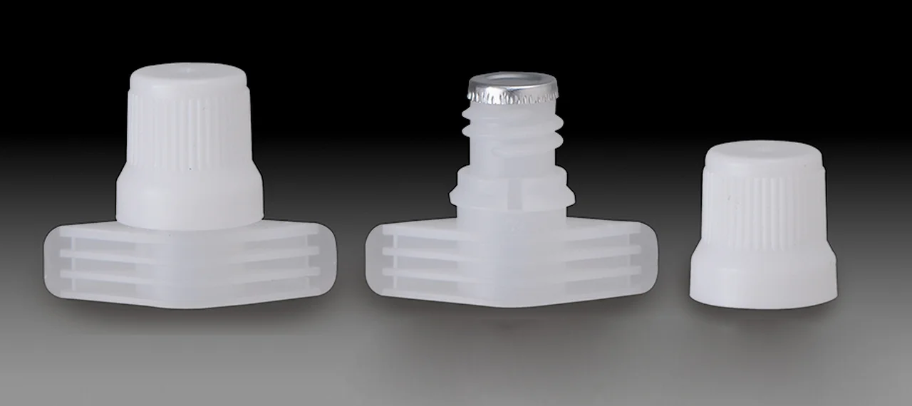
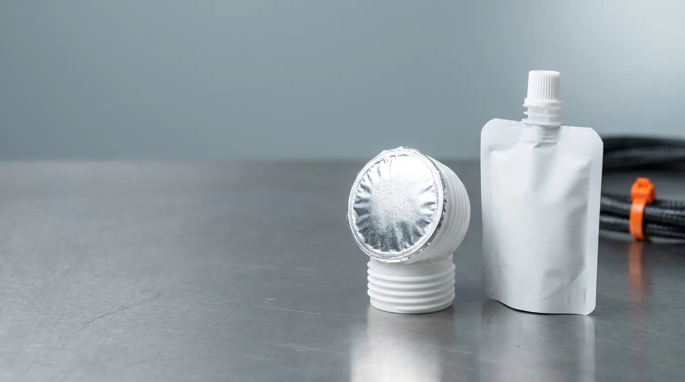
The middle part is the state that matters for the first requirement: the foil membrane is welded across the spout mouth, and the cap is off. Once a consumer peels that membrane away, this pack has no foil seal left to test.
Where the Foil Actually Sits on a Spouted Pouch
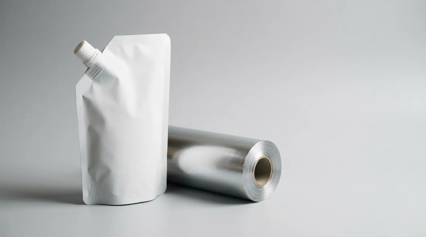
Foil as a laminate layer is a ply inside the pouch film — one aluminium layer among PET, PA, PE, chosen for barrier and stiffness. It belongs to the pouch converter, it is specified as a film structure, and it is tested as a film.
Foil as a closure membrane is a disc — what a supplier catalogue calls a heat induction seal liner — seated in the cap or supplied loose, with a polymer seal layer on one face. An induction field heats the aluminium, the seal layer melts against the spout land — the flat annulus at the top of the spout — and the disc fuses to it. That membrane belongs to the closure supplier and to your filling line, and it is tested as a closure. Almost no page on "foil spout pouch" is about this object.
Between them sits a third joint that is neither: the flange weld, where the spout fitment is welded into the pouch film. Three joints, three owners, three specifications — and the one this page is about is the membrane.
The layer stack matters for one practical reason. The membrane has to fuse to the same family of material the spout is moulded from, and the spout has to fuse to the film's seal layer — so an induction seal liner for spout pouches is never a universal part you can move between spouts. Because the seal layer is the surface that ends up against the product, the foil and its coatings sit inside the food-contact framework — EU 1935/2004 generally, EU 10/2011 for the plastic parts — which makes the liner's construction a documented item, not a consumable. The dimensional inputs that decide whether a given cap and liner pair can be specified together at all — bore, neck height, land width, thread — are the ones on a spout cap specification sheet, and they are fixed before the first induction run.
What the Induction Seal Liner Has to Prove Before Anyone Opens It
The unopened pack has three jobs, and only one of them is "does it leak".

The operation that creates the first requirement: the coil drives current through the foil, the seal layer melts against the land, and the weld ring forms in about a second — long enough to fuse, short enough that a wrong energy setting leaves no visible trace.
Barrier. In a clear pouch the membrane is often the only aluminium at the closure — it closes the pack's one opening and, over that area, is a near-absolute barrier where the film itself carries almost none. A metallised film is a sub-micron deposit rather than a foil, and in a foil-laminate pouch the film already does the barrier job, so the membrane's own barrier only has to hold the headspace it isolates. Either way the number comes from flat samples of the membrane's laminate, measured by ASTM D3985 for oxygen transmission rate and ASTM F1249 for water vapour transmission rate. Both are film tests: they describe the material, not what your sealer did to it. A perfectly good laminate welded with a wrinkle across the land tests well as a film and leaks as a closure. That figure is also what a shelf-life claim rests on, so write it beside the shelf life it supports.
Integrity. This is the closure-level question, and it is answered on whole packs. Non-destructive options include vacuum decay under ASTM F2338; destructive ones include dye penetration under ASTM F3039 for nonporous packaging and bubble emission under ASTM D3078. Each method has a detection limit, and a pass only proves the absence of leaks larger than that limit. The cluster works the same logic through in choosing a non-sterile pouch leak test; what matters here is that the limit gets written down, because your supplier and your auditor will otherwise assume different ones.
Tamper evidence. An intact membrane is also the pack's proof that nobody opened it — a visual property, checked at line speed or in a retail audit and not implied by a leak test. A pack can be leak-tight and obviously resealed.
Four failure modes account for most bad membranes, and all four are process problems rather than material problems:
- A wrinkle in the disc or on the land leaves an unwelded crescent. The weld that did form looks and measures fine.
- Contamination — a speck of product, dust or condensate on the land — blocks fusion along a line, which becomes a channel.
- Wrong substrate pairing: the seal layer is formulated for one material family and the spout is moulded from another, so the weld is a surface adhesion rather than a fusion.
- Energy outside the window: too little leaves a partial weld, too much burns through the seal layer or embrittles the foil at the edge, and both produce a pack that passes a leak test on the day and fails after a drop.
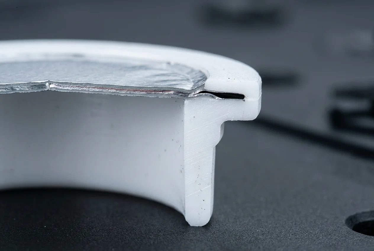
The land edge on a finished pack, with a channel under the membrane where the disc wrinkled. The fused area is continuous everywhere else — which is exactly why a peel or a burst test on this pack can come back clean.
What the Reseal Has to Prove After Every Opening
The second requirement begins where the first one ends. With the membrane gone, the only thing between the product and the outside world is a mechanical joint, and it is operated by someone in a hurry.
Three features do the work. Thread engagement — how many turns actually mate, and how much of the cap's travel compresses rather than travels. A compression element — a plug into the bore, a land the cap's top face seats against, or an elastomer pad; our 9.6 mm foil-liner caps carry a silicone pad for exactly this reason. A retention feature — a hinge that survives repeated cycling, or a valve that closes fully every time.
The variables that move reseal performance are different:
- Torque and its retention. A cap applied at a torque does not hold it: closures back off in storage as the liner relaxes, and ASTM D2063 measures exactly that — removal torque after a defined time and temperature. A cap that measures well at the capper and can lose a substantial share of its torque in the warehouse feels loose on first opening.
- Product in the thread. Sugar crystallises, pulp and particulates lodge, detergent films. Anything that dries in the thread adds friction on the way out and a gap on the way back in.
- Viscosity and surface tension. A thin, low-surface-tension liquid finds a path a paste does not — by capillary action, not by pressure.
- Orientation in use. A pouch sits upright in a fridge and upside down in a lunch bag, so the test that matters is inversion or squeeze on a reclosed pack, not a static one.
- Hand strength. The reseal has to be achievable by the weakest hand that will open the pack, which is why an over-torqued cap is a reseal failure mode rather than a safety feature.
The reseal requirement is also where cycle life lives, and that is a separate guide: how many open-close cycles a refill closure survives is covered in the refill pouch closure reseal guide. This page stays on what has to be proven.
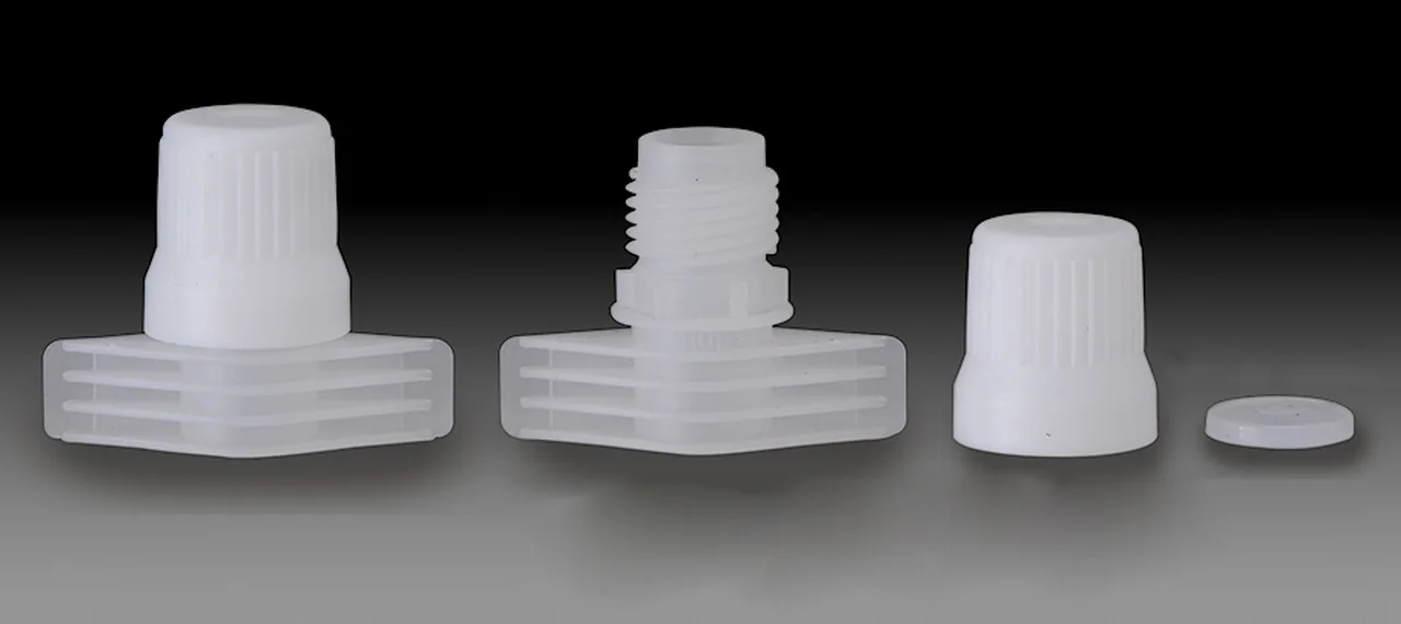
The pad on the right is the part that does the resealing. It is also the part that a foil liner specification never mentions, because while the membrane is intact the pad is doing nothing.
The Handover: How a Good Foil Seal Becomes a Bad Reseal
This is the mechanism that neither requirement's own test can see, and it is the reason the two belong in one document.
The membrane is peeled off by hand. If the weld is even slightly over-strength relative to the foil's own tensile strength, the foil tears instead of releasing cleanly: part of the disc comes away, part stays fused to the land. If the seal layer delaminates, a film of adhesive stays behind. If the consumer peels at an angle — and everybody peels at an angle — fragments collect at the land edge.
The land is now contaminated with the material that used to be the seal. The cap has to close on that surface for the rest of the pack's life. Three things follow:
- The compression element cannot seat flat, so the joint leaks at the exact spot the fragment sits.
- The fragment is foil: it does not compress, so the cap cannot conform around it the way it would around a smear of product.
- Nothing in the first requirement's test protocol sees it, because the first requirement's specimen still has its membrane on.
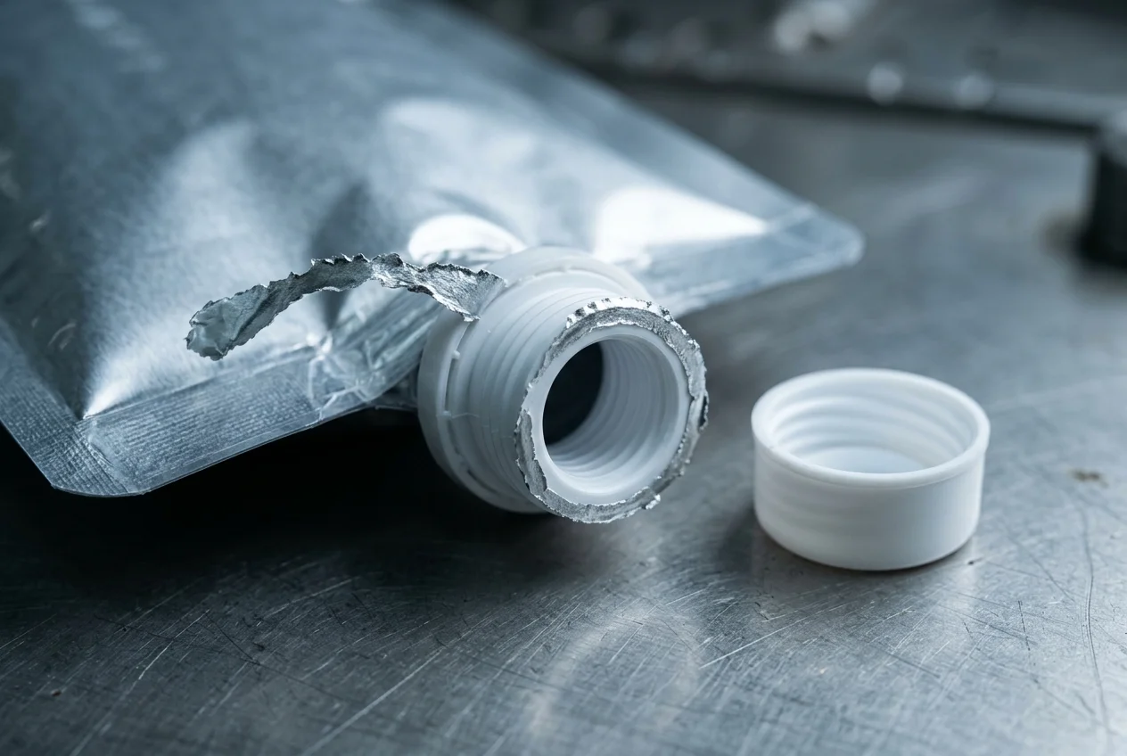
The state that neither specification covers: the membrane is off, but a strip of it is still welded to the land, and the cap now has to seal over it.
The same handover runs in the other direction with product. A viscous product that bridges the land during filling and is not wiped before induction gives you a channel under the membrane; the same product left on the land after opening gives you a gap under the cap. One contamination event, two failures, two different owners — and the fix is at the filling head, not at either supplier.
Which is why the useful question in an RFQ is not "is it leak-proof" but "at what removal torque does the membrane release cleanly, and what is left on the land when it does?" A supplier who can answer that question has thought about both requirements. A supplier who answers "our foil is food grade" has answered a different question.
When a reclosed pack leaks and the membrane is long gone, work the diagnosis back from the joint rather than from the film — the sequence is in why a pouch spout leaks after filling.
Writing Both Requirements Into One Specification
Two blocks, six lines each, and the line the buyer wrote twice becomes two lines. The left column is what release testing signs off; the right column is what the consumer experiences.
Line | Foil / induction seal block | Reseal block |
|---|---|---|
Joint | membrane to spout land | cap to spout (thread + compression element) |
State tested | unopened, filled, after the full process (including retort or hot fill if used) | opened, membrane removed, reclosed — and re-opened n times |
Method | vacuum decay (F2338) or dye (F3039) / bubble (D3078); peel force on a sacrificial pack, pulled F88-style (the ring geometry is our own) | inversion or squeeze on a reclosed pack; removal torque per D2063 after storage |
Criterion | no leak above a stated detection limit; peel force inside a band, with clean release as a pass condition | no leak after n cycles; torque inside a stated band at application and after storage |
Sample and frequency | per batch or per shift, plus start-up and after any sealer change | per batch for torque, per design validation for cycle and inversion |
Record | instrument, limit, operator, line conditions | torque value, cycle count, storage time and temperature |
Two disciplines keep those blocks honest. Write the detection limit, not the verdict. "Leak tested" is not a criterion. "No leak by vacuum decay at 50 µm equivalent, five packs per batch, written on the batch sheet" is. Keep the two results in separate columns everywhere they travel — supplier questionnaire, customer specification, validation file — because a reseal torque figure and a membrane peel force in one column will eventually be read as one number.
If your specification already separates seal strength from seal integrity for the fin seal and the flange weld, this is the closure-level counterpart — take the specimen and the conditions with it, and use the same vocabulary.
Where the Fitment Design Decides Both Requirements
The uncomfortable part is that the two requirements compete for the same few millimetres, and each dimension you gain on one side is paid for on the other:
Dimension | Push it | What it buys | What it costs |
|---|---|---|---|
Land width (the annulus) | wider | a weld ring that tolerates a wrinkled edge | room under the skirt for the plug or pad; higher peel force |
Bore | larger | faster filling, easier dispensing of particulates | less land left at the same spout outer diameter |
Cap skirt height | taller | more thread turns to engage | more plastic, taller stack, longer capping stroke |
Neck height | shorter | a lower profile on a filled pouch | fewer turns of thread before the cap bottoms out |
There is no universal land width to quote; any figure printed on a page without the bore, the film's seal layer and the product is a guess. The honest answer to "what land width should we use" is "what does your peel leave behind, and what does your cap compress against". Two levers do most of the work in practice:
- Match the weld window to the film. A spout moulded in a grade that welds at 110–130 °C widens the overlap between the film's sealing window and the fitment's, which is what lets the membrane fuse without the land or the film beside it collapsing. Ruihua's low-temperature sealing grades exist for that overlap, and the window logic is the same one described for the flange weld in spout sealing temperature.
- Decide the peel behaviour at design time. Clean release is a property of the seal layer, the land finish and the pull tab together. It is cheap to specify and expensive to discover.
The closure range behind those decisions spans 1.2 mm to 40 mm of bore over 117 models, including caps moulded to take an induction seal liner — the 9.6 mm and 22 mm foil-liner parts, several of which carry a silicone pad for the reseal side. Those are component facts, not a claim that any given cap will suit any given pouch: the pairing is decided by the film, the product and the line. The catalogue is on the spout cap range.
If you take one thing from this page into your next RFQ, take the question rather than the number: what does the membrane leave on the land, and what does the cap seal against once it is gone? Answer that and you have specified both requirements. If you would rather send us the pouch and film spec and have the closure question answered against it, that is what the sample and quote request is for.