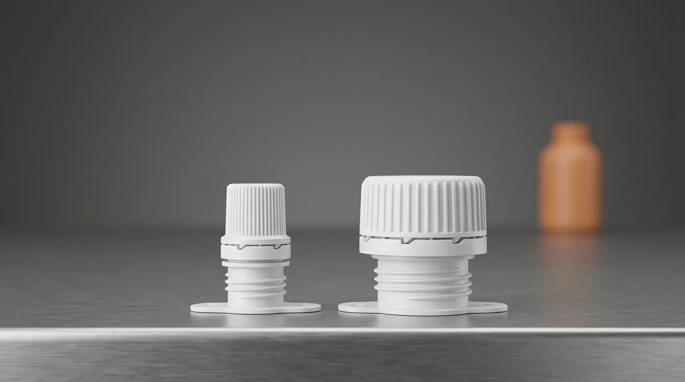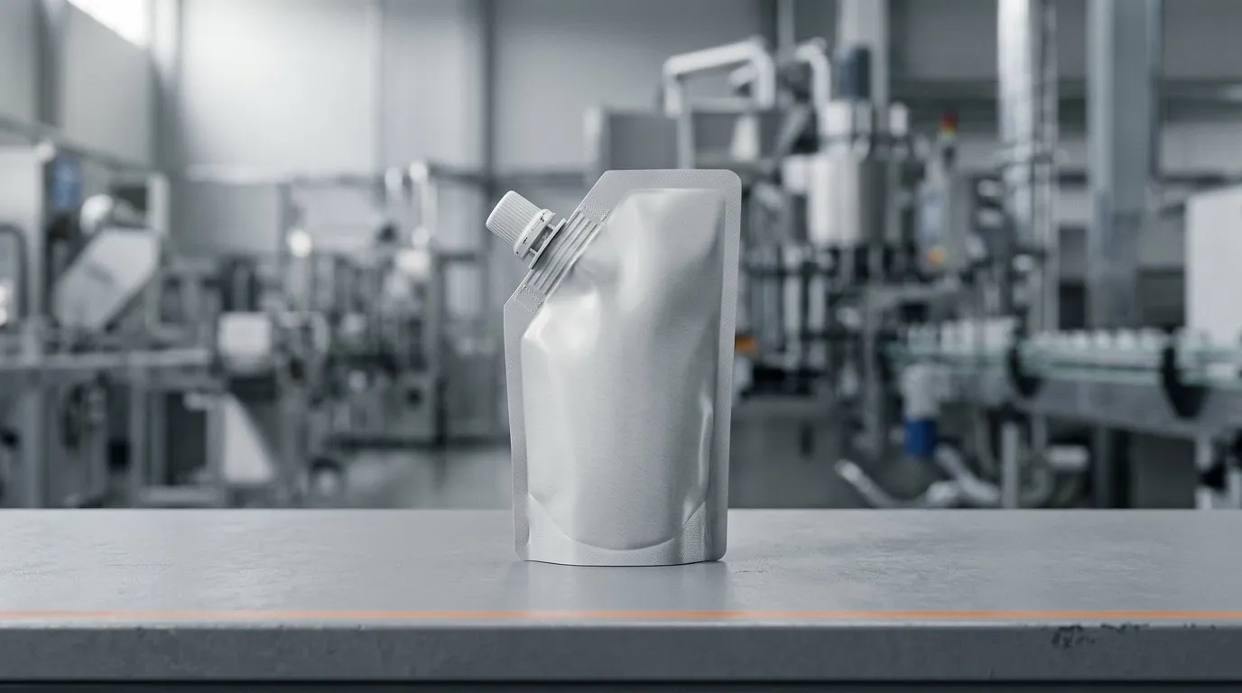

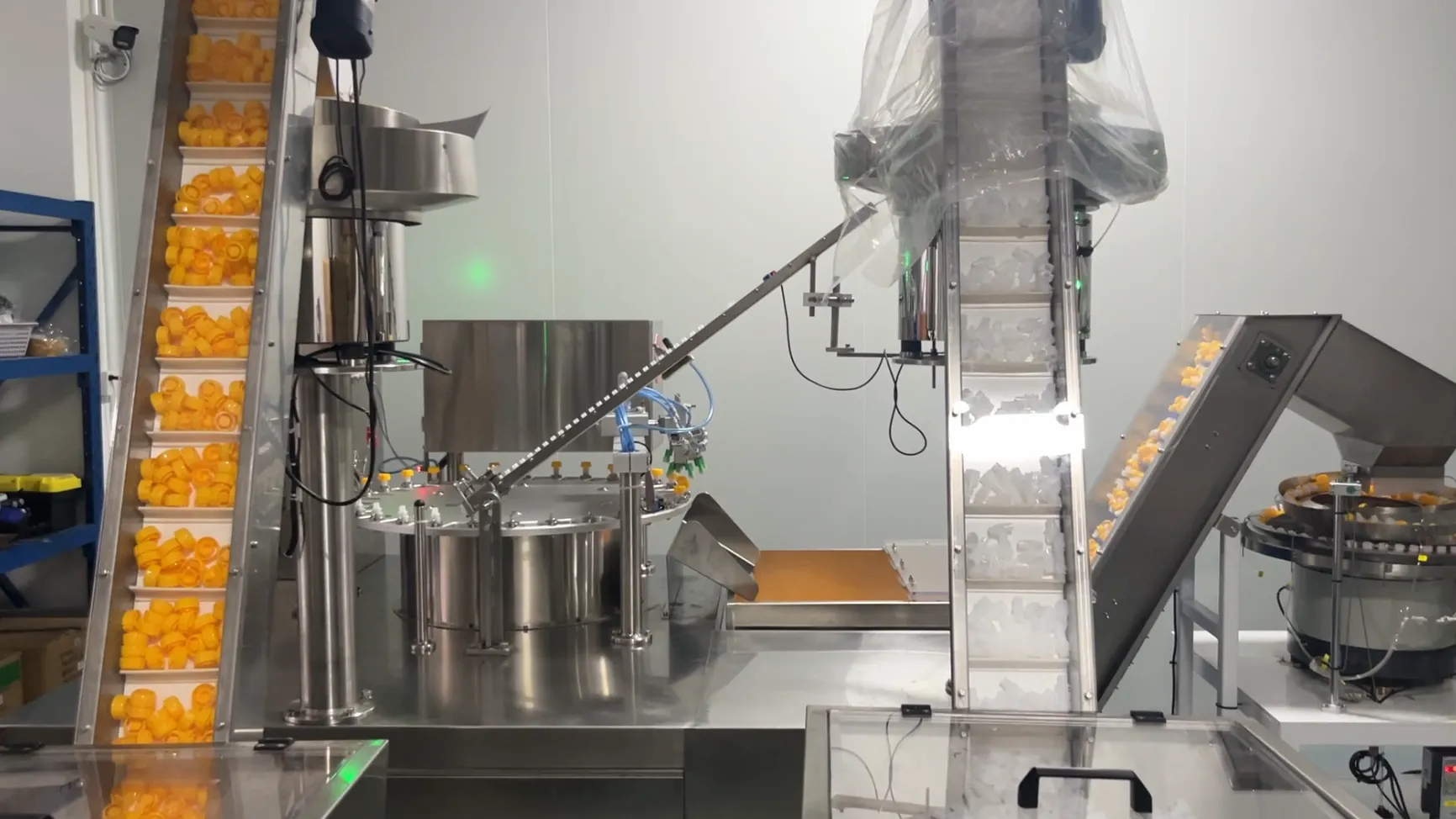
A spout that reaches the sealing jaw crooked, sits off-centre against the top seam, or never seats in the carrier is not a film problem or a sealing-temperature problem. Pouch spout alignment is a placement question: the fitment is in the wrong position or orientation at the moment the machine commits to it, and every station after inherits the error. On a running line it is usually called spout misalignment on a filling line — a defect of position, not of seal. What ships is a pack that fails later — a neck no capper can close squarely, a weld overlapping only part of the flange, a fitment that lets go inside a carton.
That distinction decides who you call first. A pack that weeps after filling is a sealing-integrity question, worked through in our guide to why a pouch spout leaks after filling. Misalignment is a position question, and it can exist in a perfectly sealed pack: the weld is sound, it is simply a couple of millimetres left of where the capper and the artwork expect the neck to be.
What spout misalignment on a filling line actually looks like
Name the defect before you touch a setting. On a spout pouch filling and capping machine — or any spout pouch filling and sealing machine running premade pouches — a misaligned spout pouch reports itself as one of five signatures, and they do not share a cause:
- Tilted neck — the spout stands at an angle to the pouch face. Angular error.
- Off-centre spout — square but displaced relative to the top seam. Lateral error.
- Shallow fitment — the spout sits low, flange not flat against the film. Axial error.
- Rotated fitment — right place, wrong clocking around its own axis, so a moulded feature or orientation lug is out of position. Rotational error.
- Dropped fitment — nothing was inserted and the pouch carries on with an open port.
Tilt, offset and a dropped fitment you can read straight off a filled pack; a shallow seat and a rotated fitment usually need a jig or a camera. So the first useful move is deciding which signature you have, and whether it appears on every lane or only one.
This article sits in the running-the-line half of our Choosing & Running Spout Caps hub, where "spout cap" always means the closure of a stand-up pouch or doypack fitment — never a gas-can spout cap.
The four links in the alignment chain
A pouch fitment is positioned by a chain, not a component. Read this as an order of suspicion, not a menu.
Link | What it controls | Signature it leaves | Measurement that confirms it | Owner |
|---|---|---|---|---|
1. The fitment — bore, neck-to-flange concentricity, flange flatness, flash at the weld face | whether a correctly presented part can sit square | the same tilt on essentially every pouch; worst on the fastest lane | dial indicator on the neck against the flange face; run-out check | incoming inspection or supplier |
2. Presentation — bowl feeder, feed rail, carrier pocket | the position and orientation the part is in when the machine takes it | reject rate creeping up across a shift; one lane only; worse as speed rises | gauge pins or feeler gauge through the rail channel; bowl track and pocket wear check | line maintenance |
3. The pouch — pick-up cups, opening, top-seam position and squareness | whether the fitment has a square seat to be inserted into | misalignment that follows the pouch, not the machine; changes with the film lot | top-seam position at entry, midpoint and exit; cup condition; vacuum level | line maintenance plus converter |
4. The closing stroke — sealing jaw, centring fingers, capping head | whether the machine holds the position it was handed | one side of the seal narrow; cross-threaded caps; torque readings spreading | jaw parallelism and closed gap; jaw-to-carrier centreline; cap torque audit | line maintenance and QA |
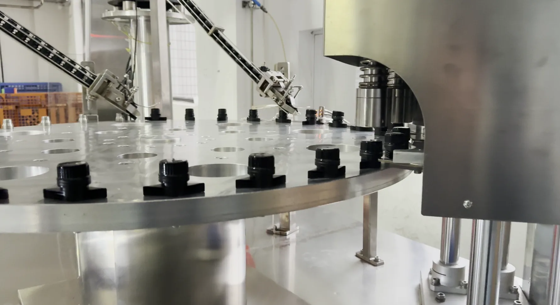
The order matters because the links mask each other, always in the same direction. A closing stroke with enough clamp force straightens a part that arrived two degrees off — until a stiffer pouch lot or a faster recipe arrives and the same machine starts producing tilt. Freezing the numbers you hold each link to is the same exercise as building a spout cap specification sheet; the difference is that this sheet runs in production.
Link 1 — the fitment's own geometry
Start on the part side even if you suspect the machine, because it is the link almost nobody measures and the one you can rule out from a drawing.
Opening diameter is not neck finish, not thread geometry and not cap outside diameter, and "8.6 mm spout" does not define enough to guarantee interchangeability. The fitment supplier's own guidance is to record the internal bore, the critical sealing surfaces, the thread or locking system and the flange dimensions and tolerances on an approved drawing, and to confirm centreline, angle, flange orientation and distance from seals on the final dieline (P&M Packaging, spout, cap and fitment selection guide). A part can pass a bore gauge and still present crooked, because the bore is not the dimension that decides squareness.
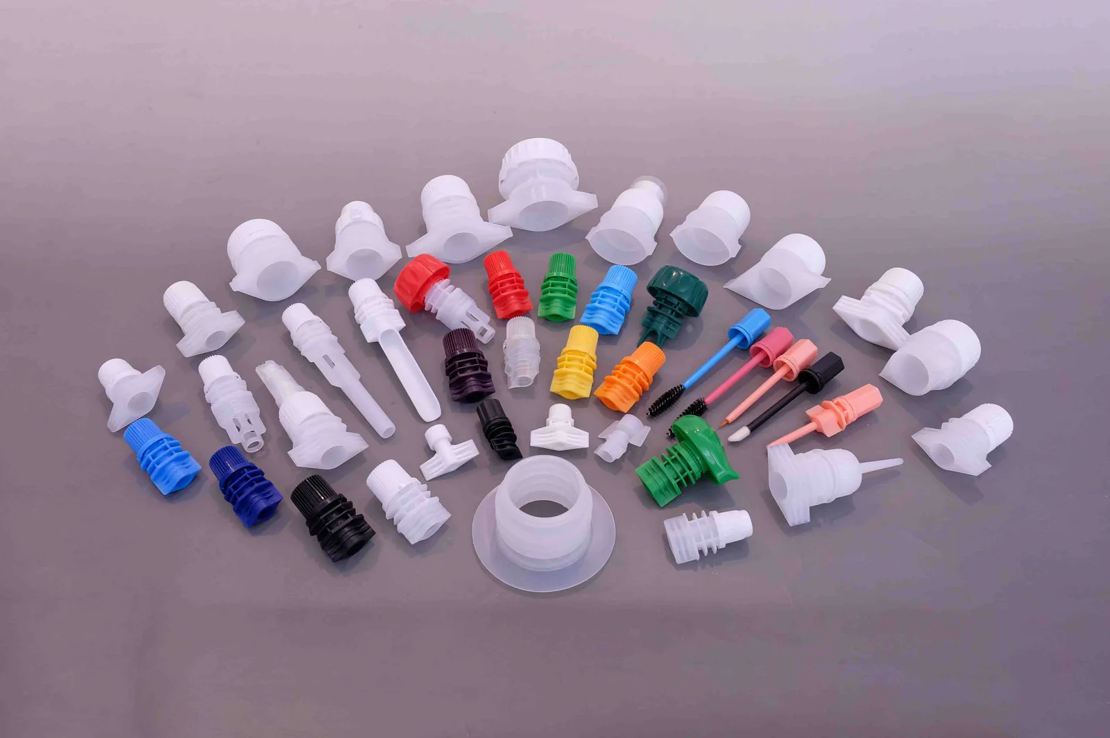
Four part-side dimensions decide whether your machine ever had a chance:
- Concentricity, or run-out, of the neck to the flange. If the neck axis is offset from the centre of the weld flange, the part is misaligned the moment it is welded — the machine did nothing wrong. It is a moulded-geometry property, it never shows on a nominal diameter, and it is the most useful number to add to a fitment drawing.
- Flange flatness and flash. A burr or a short shot at the weld face lifts one side of the flange off the film, so the part seats at an angle and the weld closes over a gap. Flatness and a flash limit both belong on the drawing, with a stated inspection method.
- Warp from cooling and gate position. Thick bosses and uneven wall sections cool at different rates, and a part that is round on the drawing can come out slightly oval. In a multi-cavity tool, test by cavity — mark them, measure separately, and see whether the defect tracks one cavity.
- Clocking. If the machine keys on a moulded feature — an orientation lug, a tare-band seam, a logo — that feature's angular position is a controlled dimension, not decoration.

For context on the tolerance side: we publish the spout inner diameter across our range as held to within ±0.1 mm of nominal, and that is the number to bring into your own stack-up. Note what it does not cover. Bore tolerance is one dimension; concentricity, flange flatness and flash are three more, and a supplier who can quote only the first has told you nothing about the other three.
One practical consequence: the more standard the fitment, the more of this is already known. A family size that runs across many pouch formats has a history behind it; a new tool for a new bore is a fresh stack-up where all four dimensions stay open until the first article is measured.
Link 2 — presentation: the feeder, the rail and the carrier
This is where misalignment is born most often, and where "the machine is running fine" is least trustworthy.
Cap feeders are judged by flow, and flow is a poor proxy for orientation. A vibratory bowl feeder can deliver an apparently perfect stream of parts while the share of misoriented parts entering the downstream track quietly rises, because orientation stability depends on the tooling inside the bowl, on track wear and on the vibration energy being delivered — not on the fact that parts are still moving (RNA Automation, vibratory bowl feeder part orientation). Getting small parts to arrive the right way up is an engineered condition, not a law of physics: the research literature treats it as a modelling and control problem in its own right (Development of a model for part reorientation in vibratory bowl feeders with active air jet tooling).
Once a part leaves the bowl it travels down a rail, and the channel is a fit. A rail cut for one spout diameter and one pouch pitch holds the neck at the angle the channel gives it; open the channel by a fraction of a millimetre and the part is free to lean, close it and it jams or shaves. On the line, that gap is the difference between a fitment tracking true and one that wobbles.
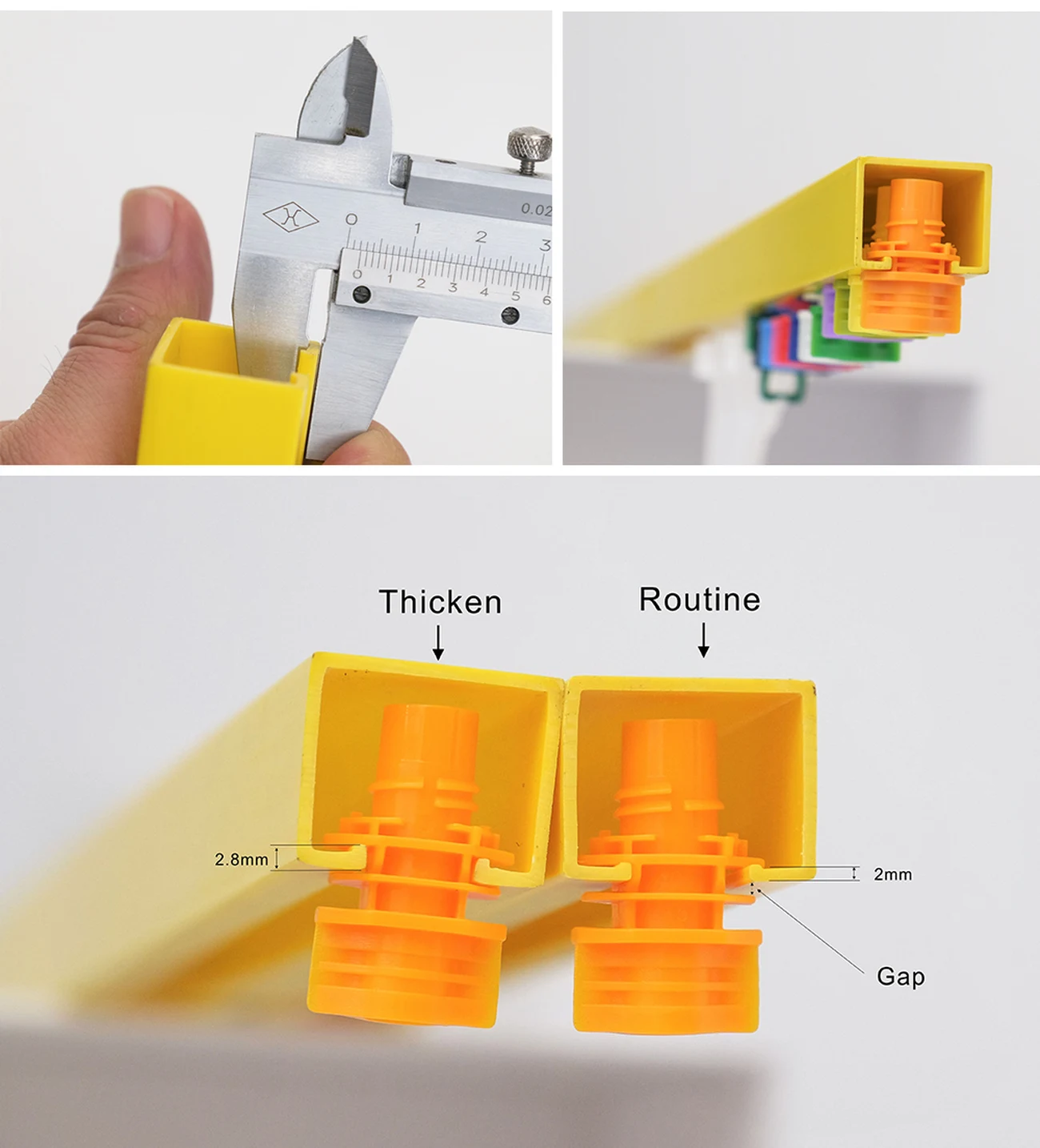
Four things wear in this link, and all four are cheap to check:
- The rail channel. Grooves get worn into the channel walls by the same part passing a million times. A worn channel is wider than its drawing — exactly the condition that lets a spout lean. Check with gauge pins, not by eye.
- The bowl track and tooling. Worn tooling stops separating correctly oriented parts from misoriented ones, so the reject rate climbs with no recipe change.
- Carrier pockets. Polymer pockets wear oval, and a pocket that has drifted from its nominal centre presents the fitment slightly off every cycle.
- Sensors that confirm the wrong thing. A presence sensor answers "is a part here", not "is the part square". Machines close that gap — spout-position detection and optional vision-based spout alignment verification are catalogue items on fitment insertion systems (Pro Pac, Matrix Pacraft TX-100SP-1) — and a line relying on the rail alone closes it with clamp force instead.
All of the above is about holding position within one size; what changes when the size itself changes is a separate problem, covered in our changeover article. If you are buying hardware for this link, a spout rail specified together with the pouch pitch costs far less than the rejects a worn channel produces.
Link 3 — the pouch: pick-up, opening and insertion depth
The third link changes with the weather, and it is the one that makes people believe the machine is haunted.
A spouted pouch has to be picked up, held and opened before a fitment can be inserted to depth, and every step is a mechanical event with a tolerance. Pick-up cups lose diameter and gloss as they wear, delaying the moment the mouth opens relative to the rest of the cycle, so the pouch reaches the insertion station a fraction late and a fraction askew. Vacuum below baseline pressure lets it slip during transfer. Both worsen as speed rises, because the margin between release and insertion shrinks — which is why a line that runs square at low output and drifts at production speed is usually reporting wear, not a settings error.
The pouch itself is a variable, and stand up pouch spout alignment is never a machine property alone. Laminate stiffness and gauge differ between film lots, the top seam does not always sit in the same place relative to the pouch edge, and a pouch slightly off nominal shifts the seat the fitment lands in. Insertion depth belongs here too: the flange should arrive flat against the film, and on a spout insertion machine a stroke that bottoms out early — or a pouch held too high — leaves the spout shallow even though the machine did exactly what it was programmed to do.
There is a useful diagnostic in the difference: a pouch-side fault shows as a distribution, a machine-side fault as a drift. If the reject rate jumps when a new film lot is loaded and stays there, look at the pouch. If it climbs steadily through a shift and resets after maintenance, look at wear. That distinction prevents the most common wasted afternoon on a spouted-pouch line: adjusting a healthy sealing station to compensate for a pouch that was never presented square. It also keeps you out of the neighbouring problem — a shallow or crooked spout can leak too, for different reasons, which the leaks article above separates.
Link 4 — the closing stroke at the sealing and capping station
Now the station, which is usually the symptom's address rather than its cause — and occasionally genuinely at fault. Spout fitment insertion alignment is decided here as much as at the feeder: this is where the position is held or lost.
Four mechanical facts decide whether spout sealing station alignment survives the stroke:
- Jaw parallelism and closed gap. Jaws that are not parallel close progressively across the weld face, so one side of the flange is welded while the other is still being approached. On a mono-material PE pouch in the low-temperature band, that asymmetry shows up as a narrow seal or a heat-damaged edge rather than as obvious misalignment. Spouts engineered to seal at 110–130 °C to protect a PE seal layer are only as good as the jaw delivering that temperature evenly (low-temperature sealing spouts).
- Centring fingers and guides. These exist to correct small offsets, and they are designed with a working range. Once a part arrives outside that range, the fingers no longer centre it — they clamp it crooked, and the pack looks as though the machine deliberately tilted the spout.
- Stroke and dwell timing. A servo axis that was not homed after a changeover, or a recipe recalled without its preset, still closes on the part. The five-interface match behind that behaviour is the subject of our article on whether a spout runs on your existing sealing machine; what matters here is that the match is verified once, while alignment drifts daily.
- The capping head. Cap application is an alignment job too. A head whose axis is offset from the spout axis cross-threads, and cross-threading shows up as a torque reading that scatters rather than as a visible defect — so a torque audit is also an alignment audit.
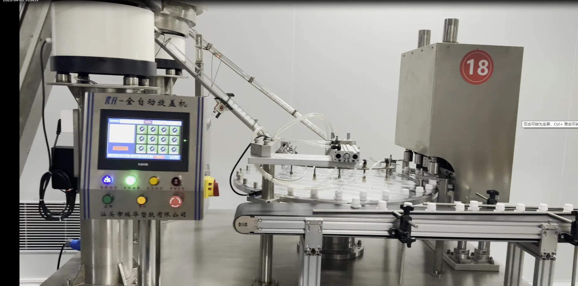
The trap here is over-correction. Raising clamp force or tightening a guide to stop a crooked spout works — on that pack, at the cost of turning a soft fault into a hard one: a part that would have run slightly tilted now runs slightly crushed. Fix the upstream link first, then return the station to its design setting and re-qualify it.
How to measure pouch spout alignment so you fix the right link
Everything above is guesswork until something is measured, and this is the step the available guidance skips: causes are easy to find, what to gauge is not.
Choose a datum and write it down. Pouch spout alignment means nothing until it is measured against one: the rail centreline, the carrier pocket centre or the seal-jaw centreline — pick one and record which. "The spout is off" is an opinion; "the neck is 1.4 mm left of the jaw centreline, at entry" is a work order.
Match the instrument to the quantity. Lateral offset is fastest with a feeler gauge between the neck and a guide, or a dial indicator on the neck with the pouch held in a fixture. Angular tilt needs two readings: touch the indicator at two known heights, subtract, and divide by the height difference. Insertion depth is a depth gauge from the flange face to the pouch top seam. Clocking needs a reference mark and an index — paint it, or use a moulded feature.
Contact gauges are fine for a first-off check and useless for a rate. To learn how often this happens rather than whether it does, the measurement has to happen at production speed — a non-contact gauge. That is a solved application: machine builders sell alignment verification as an option on fitment insertion systems, and vision systems measure centre misalignment by fitting a circle to the inner and outer peripheries of a part rather than by edge detection alone (KEYENCE, machine vision examples in the commodities industry).
Sample at the speed you sell. Twenty packs measured at half output tell you nothing. Run at target rate, pull thirty consecutive packs, measure the same feature on all of them.
Two numbers end the argument. The displacement, in millimetres, and the reject rate, as a percentage of cycles. Everything else — how it "looks", which shift is worse, whether the new lot is "fine" — is noise until those two exist. Keep them on a control chart: a step change points at a setup or a lot, a trend at wear, and scatter neither explains at grip and timing. The part side gets the same treatment on the way in, where bore, concentricity and flange flatness belong in your inspection plan — the discipline our quality control process applies to the spouts themselves.
There is no industry-wide misalignment tolerance to look up. A number you can defend is your station's own capability plus your part's own capability, measured on your line; any figure quoted without those two is somebody else's line.
That measured number is what you write into the line documentation as the pouch spout placement tolerance for the format — not a catalogue value somebody else's machine holds.
Re-qualifying the line after you change something
Every alignment fix is a change to a validated setup, and the useful habit is to treat it as one.
Change one thing, then re-run the first-off routine: pull the first packs at production speed and measure spout position, insertion depth and cap torque against your recorded numbers. Then verify the weld. Dye penetration is the standard go/no-go method — a penetrant is applied locally to the seal edge and the pack is inspected for dye migration; the test detects a leak equivalent to a channel formed by a 50 µm wire, and the standard notes that such leaks are "frequently found at seals between package components of the same or dissimilar materials" (ASTM F3039-23). A fitment weld is exactly that kind of component seal. Pair it with a hold or squeeze test and a pressure-decay check and the pack is qualified, not assumed.
There is a wider principle here, and the packaging industry already writes it down. ISO 11607-2:2019, the medical-device packaging standard, sets out validation requirements for the processes that form, seal and assemble a package, with process changes and revalidation handled by its 2023 amendment. It is written for terminally sterilized devices, so it is not your compliance regime; what generalises is the sequence the standard's own logic implies — validated process, documented change, re-validation before release — instead of a trial run and a shrug.
Two more things belong in the same loop. Re-check cap torque whenever the capping head has been disturbed: torque is the fastest indicator that the head axis has moved. And on the way in, add whatever the investigation taught you to your fitment inspection: if the fault tracked one mould cavity, that cavity's parts should be measured on arrival.
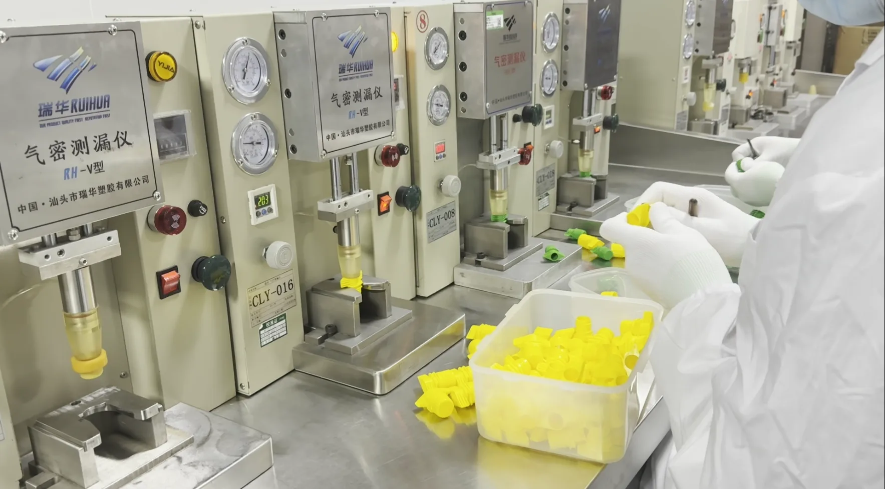
We keep both ends of this in-house — moulds are made here, and parts are checked on dimensional and air-tightness equipment — so a concentricity or flange-flatness question gets a measurement, not a reassurance. If it is the leak test you are chasing rather than the placement, the weld's temperature side is covered in our article on spout sealing temperature.
A triage order for the next time it happens
Most spout misalignment filling line problems get diagnosed in the wrong place twice before they are diagnosed in the right one. Every spout pouch alignment question divides on the first line below, so work down this list before changing a setting:
- One lane, or every lane? One lane points at that lane's hardware — rail, pockets, guide, capping head. Every lane points at the fitment lot or the pouch lot.
- Constant, or getting worse? Constant in one direction is a centreline or setup error: something was moved and not returned. Worsening across a shift is wear.
- Did it start with a new film or fitment lot? Then measure the pouch and the part first: top-seam position, film gauge, bore, concentricity, flange flatness.
- Only above a certain speed? That is grip and timing, not geometry — cups, vacuum, release timing.
- Is the cap crooked as well as the spout? Then the error is upstream of both, because two independent stations rarely fail in the same direction by coincidence.
- Measure the displacement, change one thing, re-run first-off. One change per cycle; two changes and you learn nothing about either.
If you want the compatibility questions out of the way while you investigate, the pouch fitment compatibility tool puts the interface checks in one place — the same interfaces the line is failing to hold.
Frequently asked questions
Is a crooked spout the spout's fault? Usually not — most placement faults are presentation or station faults and respond to maintenance. But the part side is the one nobody measures, and a concentricity error or a flange burr produces a permanent tilt no adjustment removes. Rule it out with a dial indicator before spending a shift on the machine.
Can one lane be misaligned while the other runs clean? Yes, and it is one of the most useful signals you will get. Two lanes fed by the same bowl but served by separate rails, carriers and jaws have separate wear histories, so a single-lane defect points at hardware on that lane, not at the recipe.
Does a misaligned spout always leak? No. A tilted or off-centre spout can be welded correctly and pass a leak test on the day, then fail later because the capper cannot close squarely on a tilted neck, or because the weld overlaps less flange than designed. Placement and integrity are different questions with different tests.
Will slowing the line down fix it? It hides it. Lower speed restores the timing margin that worn cups or a worn channel ate, so rejects drop while the wear accelerates. Use speed as a diagnostic — where does it start? — not a remedy.
What should the fitment drawing carry so this does not happen again? Five things beyond the nominal bore: the bore with its tolerance, neck-to-flange concentricity or run-out, flange flatness, a flash limit at the weld face, and the angular position of any feature the machine keys on. That is the set this failure mode uses.
Placing the fitment straight, and keeping it there
Misalignment is a placement defect with four possible homes, and the fix is almost never where the symptom appears. The station reports the error; the fitment, the rail, the pouch or the closing stroke produced it. Measure the displacement against a datum, decide whether you are looking at wear or a setup error, and repair one link at a time.
If you are working a placement problem now, send the drawing you have and the displacement you are measuring. Our spout fitments run across a 1.2 mm to 40 mm bore range in food-grade PP and PE, made in our own mould shop and checked on dimensional and air-tightness equipment, and we will tell you which of the four dimensions above your drawing is missing before you change a setting. Request samples or a quote and we will answer against your pouch format.