
Why pouch sealing machine compatibility is five separate questions
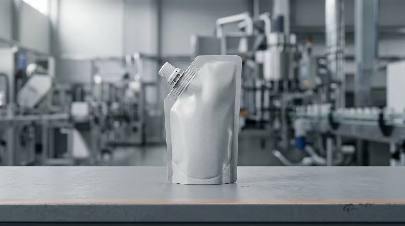
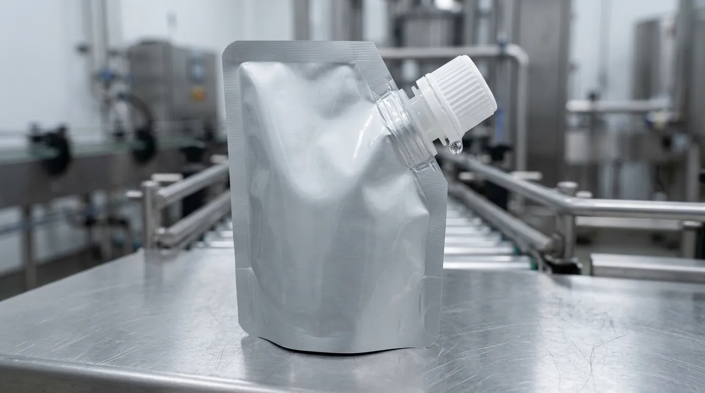
The sample sealed on the bench. On the line, caps jammed in the feeder, one side of the top seal ran narrow, and the torque readings spread wider than anyone could explain. Nothing was defective. The doypack spout simply had five separate interfaces with that machine — the stand-up pouch film, the sealing station and the cap feeder — and only one of them had been checked.
Pouch sealing machine compatibility is not a property of the spout and not a property of the machine. It is the match between five interfaces on the line you already own: bore to filler nozzle, flange and weld face to the sealing jaw, neck height and cap profile to the feeder, resin to the film's seal layer, and model mix to changeover. Every one of them can be checked against data you already have, before you place an order.
Most buyers ask one question — "will this fit my machine?" — and get "yes, it's standard". That answer describes the spout in isolation. The table below is the version that survives contact with a production line.
Interface | What it actually decides | The number you need | Who has it |
|---|---|---|---|
Bore vs your filler | whether the nozzle enters and seals, and how fast the pouch fills | nozzle outer diameter, fill method | you + machine builder |
Flange and weld face vs your sealing jaw | whether the weld closes completely, and whether the jaw can reach it | flange outer diameter, weld face width, jaw length | you + spout supplier |
Neck height and cap profile vs your cap feeder | whether caps feed, orient and torque | neck height above the flange, cap diameter and style | you + spout supplier |
Resin vs the film's seal layer and your process | the shared temperature window, and whether the pack survives retort or hot fill | film seal layer, process temperature and time | you + film supplier |
Model mix vs changeover | how many formats the line can actually run in one week | models per order, change parts, stock position | you + spout supplier |
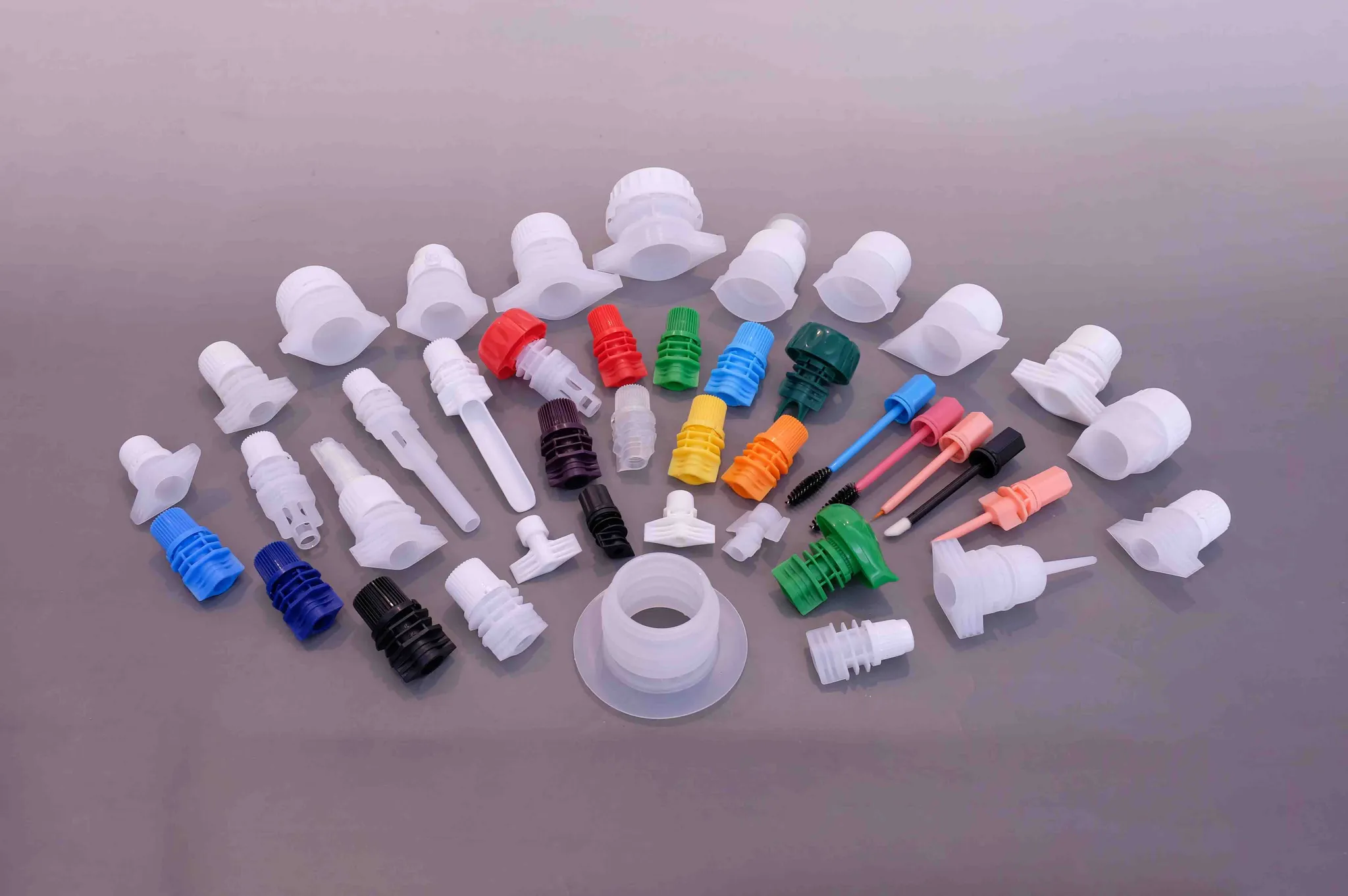
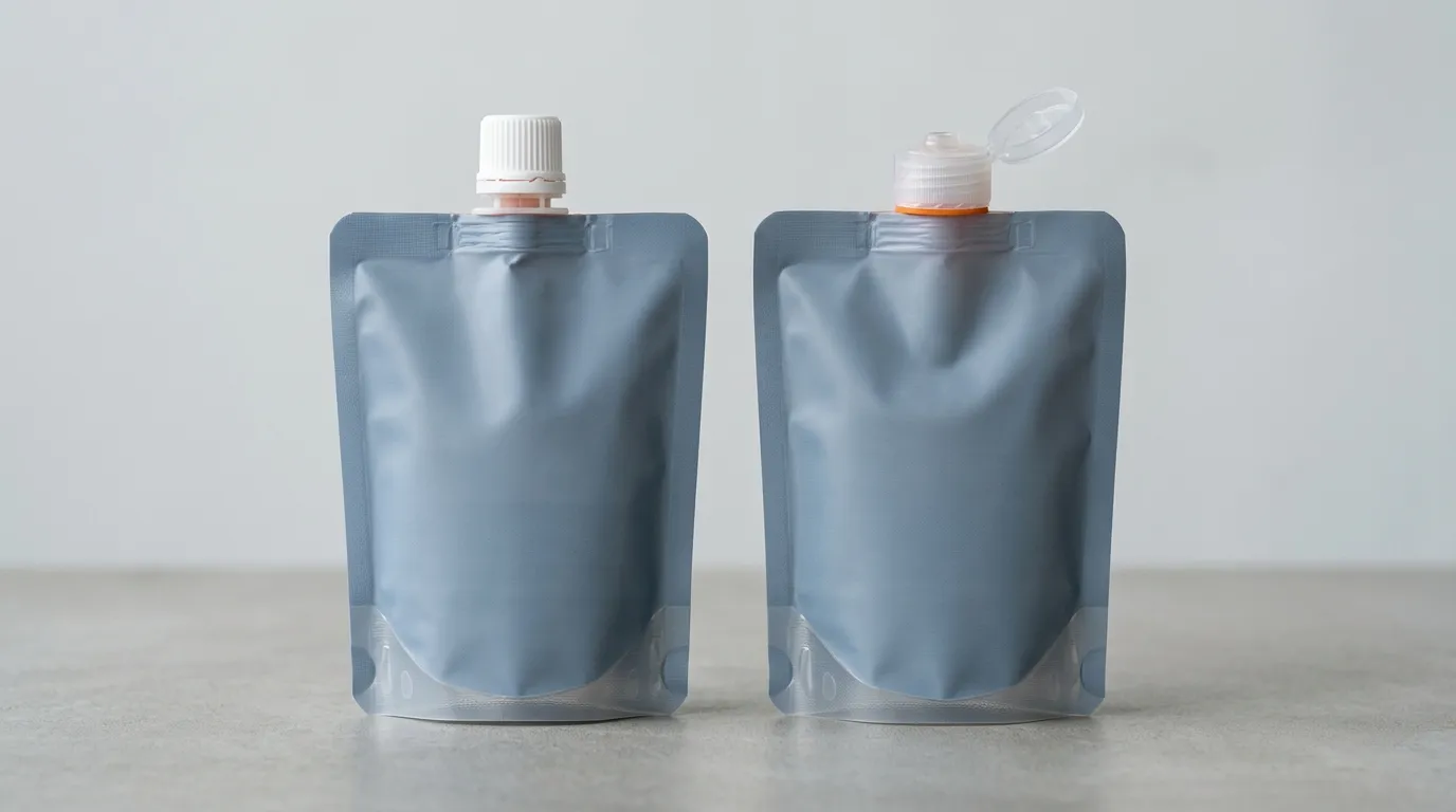
One product family, many interfaces. Bore, flange, neck height, cap style and resin vary independently — which is why a single "standard spout" answer does not exist.
Everything below assumes you already run a line and a pouch format, and only the fitment is new. If you would rather work the five interfaces as a guided questionnaire first, the pouch fitment compatibility tool asks four questions and returns the same numbers.
What to capture on your own line before you talk to anyone
The spout cap selection and running series covers how a fitment gets chosen. This page is about proving the choice on a line that already exists — the stand-up pouches and doypacks you already run. A spout arrives later and changes that picture in two ways: it takes area out of the top seal, where a flange and its weld face occupy film the top seal used to own, and it is a physical part that has to be fed, placed, welded and closed inside the machine's existing geometry.
So the useful first move is not asking a supplier what fits. It is writing down what you have.
Write this down | Where to find it | Why the spout decision needs it |
|---|---|---|
Pouch format and finished dimensions | your current spec sheet | determines the flat area available for flange plus top seal |
Top seal width and jaw length | machine manual or a jaw measurement | sets the ceiling on flange outer diameter |
Film structure and seal layer | film supplier's spec | the spout has to weld to that layer, at that layer's window |
Filler nozzle outer diameter | a caliper on the nozzle | the bore must admit it if you fill through the spout |
Fill route | line documentation | through-the-spout filling and open-top filling have different bore constraints |
Cap placement method | observation | gravity track, bowl feeder, pick-and-place and rotary pockets reject different cap shapes |
Capping torque setting | machine settings | torque is a function of cap diameter and thread, not a constant |
Product viscosity, particle size, foaming | your product spec | a 3 mm bore and a diced vegetable are incompatible regardless of what the machine can do |
Process after sealing | process sheet | retort, hot fill and pasteurization each set a floor the spout must survive |
Models you intend to run | your own commercial plan | every extra cap format becomes a change part |
If you only have twenty minutes, the two lines that matter most are top seal width and cap placement method. Those are where an otherwise excellent fitment fails.
It is also worth knowing which machine class you are on, because the classes fail differently — this is the question behind "small" and "industrial" pouch sealing machine compatibility. The same spout behaves differently on each.
Line class | What it does with the fitment | What it demands of the spout | Where it usually breaks |
|---|---|---|---|
Manual or bench insertion unit | operator places the fitment, machine closes the weld | handling-friendly flange, no loose orientation | cycle time, weld consistency between operators |
Semi-automatic single-station sealer | fitment presented in a fixture, one weld per cycle | fixture geometry matched to flange and neck | fixture changeover when cap format changes |
Inline insertion station on a premade-pouch line | fitment fed, placed and welded inside the index | feeder-compatible cap shape, consistent neck height | feeder jams, placement misses |
Rotary capping head on a filling line | caps fed in bulk, oriented, torqued | cap diameter and height within head range | torque drift, cross-threading |
Form-fill-seal with fitment applicator | fitment welded during film travel | weld window shared with film and line speed | dwell time too short at high speed |
On the common question of which machine, or which brand of machine, is best: that question rarely resolves at brand level, and a fitment supplier is not the right source for it anyway. Ask your machine builder whether the class you run can present the fitment repeatably at your speed, with the fitment sample in hand.
Vacuum sealing and air removal are a separate project. A vacuum or gas-flush stage changes the headspace and the fill, but it changes none of the five interfaces below: a fitment that fits before the vacuum stage fits after it.
Treat every figure on this page as a spout-side number. Machine settings are specific to your line, and nobody can hand you a temperature for a machine they have not seen.
Interface 1: the bore has to meet your filler
The bore is the first interface because it is the hardest to change later. Two fill routes exist, and they put the bore under different loads.
On an open-top line, the pouch is filled through the open top and the fitment is inserted and welded afterwards. The bore only has to satisfy the dispensing end — how fast the consumer can pour, and whether the product flows. On a through-the-spout line (also called through-fitment filling), the filler nozzle enters the fitment itself, fills, and retracts — this is the spout pouch filling machine case, and now the doypack spout has to admit your nozzle, with clearance, at line speed.
Pouch sealing machine compatibility at this interface reduces to one measurement: your filler nozzle's outer diameter against the spout's inner diameter. Measure the nozzle, not the drawing. Nozzles wear, get replaced, and are sometimes re-machined by a maintenance team that did not update the file.
Our own range runs from 1.2 mm to 40 mm of inner diameter across 117 models, so the catalogue will almost certainly contain a nominal match. Nominal is not the question. The question is which side of the tolerance the part lands on, because a nozzle that fits a spout at the low end of a range and jams on a spout at the high end is a real failure mode on a line that buys in batches.
This is where a published tolerance earns its keep. We publish our spout inner diameter as held to within ±0.1 mm of nominal, and that figure is the one to enter into your own stack-up: nozzle diameter, spout bore, tolerance on both, and the clearance you need for a smooth insertion. If your stack-up leaves less clearance than your maintenance team can guarantee, the bore is wrong for that line — not marginal, wrong.
Three practical constraints sit on top of the diameter:
- Viscosity and headspace. A high-viscosity paste filling through a small bore runs slowly, and the fill level has to leave room for the neck. If the fitment is at the top of the pouch, headspace is not a detail you can tune later.
- Particles. Anything with particulates needs a bore with real clearance over the largest particle, or a large-bore fitment. A 22 mm to 30 mm bore is the usual answer for grain, pet food and diced product; a 1.2 mm to 5 mm bore belongs on cosmetic, pharmaceutical and dosing work, not on chunky food.
- Foaming. Foam in the neck after filling becomes product in the weld zone at the next station. That is a seal failure that looks like a spout defect and is not one.
If your line fills through the fitment and your nozzle diameter and your fill head are not in the same document, sort that out before you ask anyone for a sample. Sizing a bore against a filling head is worked through in the spout cap diameter guide.
Interface 2: the flange and weld area against your sealing jaw
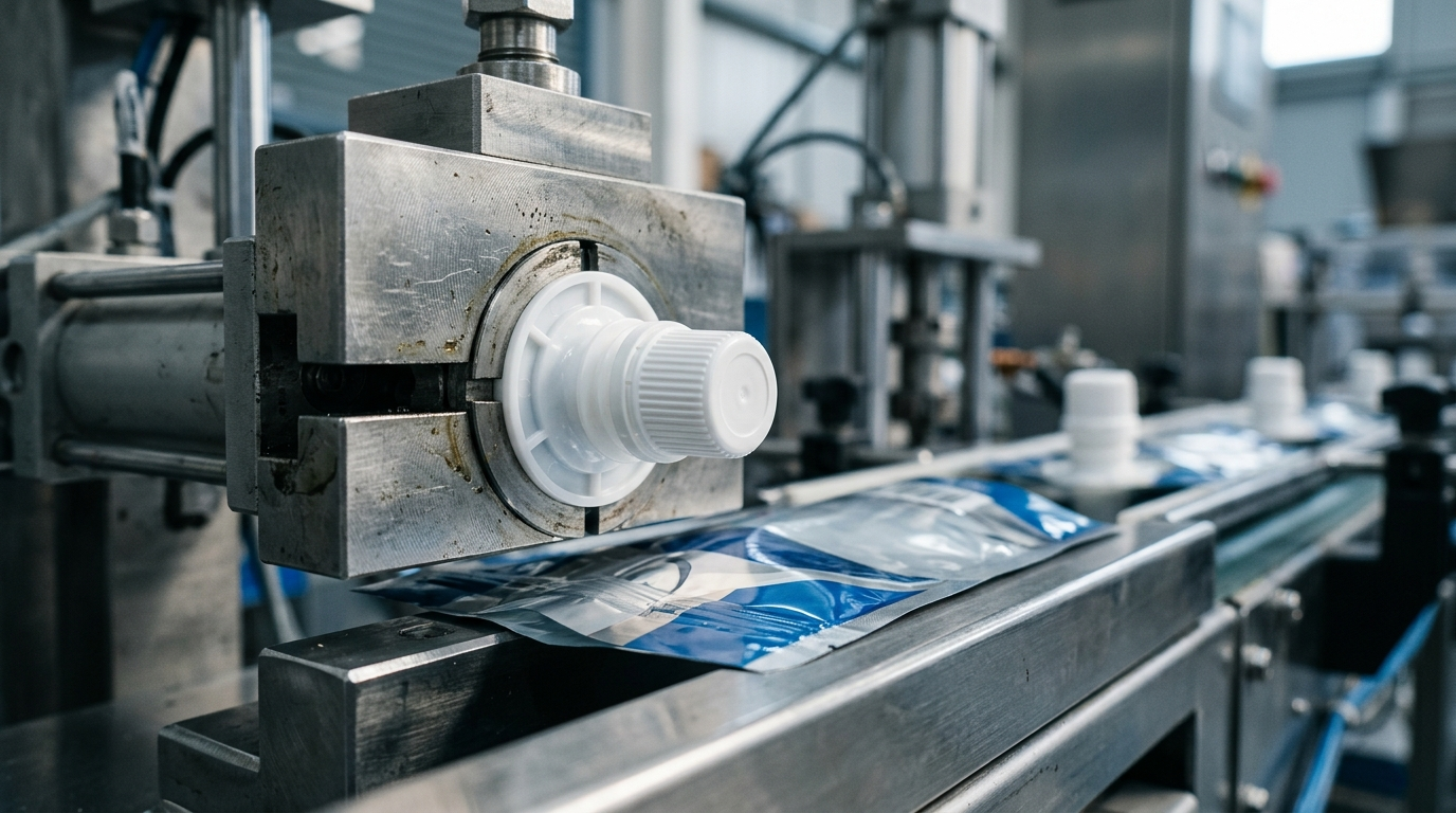
The seal is where the fitment stops being a component and becomes part of the package. Mechanically, the station holds the pouch, presents the fitment into the film, and applies heat, pressure and time until the flange's weld face fuses with the film's seal layer. Three geometric facts decide whether that can happen on your machine.
The flange has an outer diameter, and it competes with your top seal. A flange sitting in the pouch top consumes film that the top seal otherwise spans. If your top seal is narrow, a wide flange plus its weld face can leave less overlap than your seal specification allows. Measure the flat area across the pouch top, subtract the flange diameter, and see what is left. This is the single most common geometry conflict we are asked to solve after a failed trial. If your line prints a date code on the seal, the print head is competing for that same flat area.
The jaw has to reach the weld face, and the neck is in the way. Most sealing jaws close on a flat plane. A fitment with a neck standing 10 mm or more above the flange means the jaw either needs a relief, or the fitment sits in a nest or fixture that presents the flange flush while the neck goes through it. Whether your machine has that nest, and whether it has change parts for a different flange, is a machine-side question — but the fitment's neck height and flange profile are the numbers that answer it. If that station is something you are choosing rather than already owning, the spout sealing machines page covers the hardware half of this interface.
The weld needs a temperature window that the film and the spout both accept. Our low-temperature sealing grades are engineered to weld at 110–130 °C, which is what makes an all-polyethylene recyclable pouch possible: the spout can fuse to a PE seal layer without the film's structure collapsing. Our retort-rated models hold their geometry through a 121 °C process, which is a different property measured at a different moment — one is a fraction of a second during welding, the other is minutes after filling. A single "recommended temperature" on a datasheet cannot cover both, and if a supplier gives you one number, ask which of the two it is.
The film side has its own window and your line has a dwell time. Compatibility lives in the overlap of three windows — film, spout, machine — and the overlap narrows as line speed rises, because dwell time falls.
Two standard methods keep this from becoming an argument. ASTM F2029 defines how to make laboratory heat seals so that sealing conditions can be compared at all; ASTM F88 defines how to measure the resulting seal strength. Ask for both: a seal made at your conditions, and a seal-strength number from it. A supplier who can only report a temperature is reporting an opinion; one who can report seal strength at stated conditions has handed you something you can put in a validation file.
Interface 3: neck height and cap profile vs the cap feeder
This interface is usually invisible until the line runs at speed. On the bench, an operator picks a cap up and turns it the right way. A cap feeder cannot be told what "right way" is — it has to be built so that only the right way is physically possible.
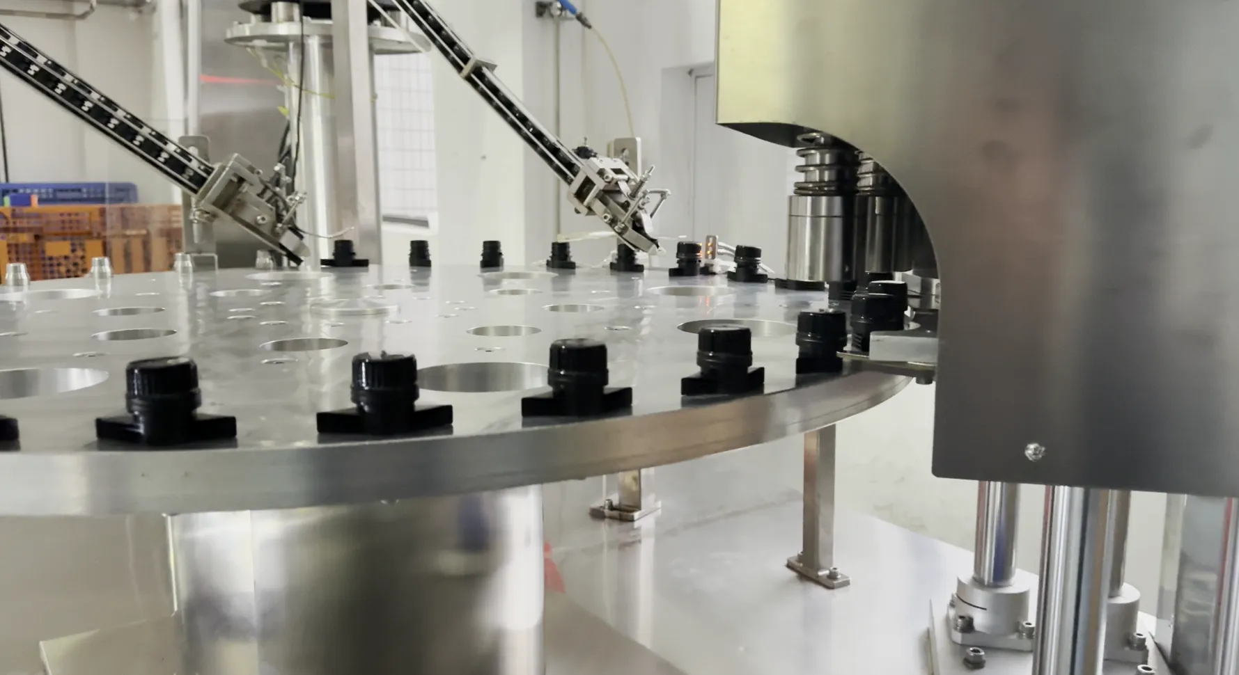
Orientation is mechanical, not a setting. Pockets, tracks and escapements accept some cap shapes and reject others — and this is the station that decides which.
Feeders sort parts by shape, and the shapes that sort well are the boring ones. A symmetrical screw cap with a flat top and a defined diameter tracks and orients dependably. A long-nozzle spout, a mushroom-shaped anti-choking cap, a flip-top with a hinge, or a cap with a brush head has at least one asymmetric feature, and asymmetry is what a gravity track will find a way to jam on. That does not make those closures unusable — it makes feeder tooling a design input rather than an afterthought. If your feeder is fixed tooling and your new cap is a different shape family, the comparison you need is cap-shape-to-feeder, not cap-shape-to-pouch.
Four measurements carry this interface:
- The spout cap dimensions that matter here: cap diameter and height, against the feeder's track and escapement range.
- Neck height above the flange. It has to be tall enough for the cap to seat and for the capping head to reach, short enough to clear the headroom, and positioned so the pouch's own top fold and any zipper profile do not collide with it. This is where a fitment that is fine on a flat pouch gets caught on a gusseted or zippered one.
- Cap weight. Very small caps on very small bores are light enough to be blown out of alignment by air on a fast line.
- Thread or engagement geometry, because torque is a function of diameter and thread form together. A capping head set for a 22 mm cap will not deliver the same torque on a 9.6 mm one, and the target torque changes with it. Torque that drifts after a changeover is one of the most common post-launch complaints we see, and it is almost always a head setting, not a cap defect.
If you run more than one cap format, the honest question is how many change parts that costs: feeder tooling, escapement, capping head, and the nest at the sealing station. Formats sharing a neck height and diameter cost nothing to switch between; formats that differ in both cost a changeover every time. Two line-side components belong in the same review: the stand-up pouch guiding rail, which positions and opens the pouch ahead of the insertion station, and the nest or fixture that presents the flange to the jaw.
Interface 4: resin, seal layer and the process window
The resin question is a materials question, not a sourcing one, and it has two halves.
Sealing half. The fitment has to fuse with the film's seal layer. Polyethylene is the usual answer for a PE seal layer and the common choice in this product family; polypropylene brings higher heat resistance, which is what retort work needs. PP is also the harder of the two to hold in shape — shrinkage during molding is less forgiving — which is why retort-rated spouts are difficult to mold consistently. If you are moving to a mono-material PE pouch for recyclability, the constraint is that film and spout must both weld below the temperature at which the film's structure suffers, which is the reason low-temperature sealing grades exist. The sealing temperature window is worked through separately if your film and process are still being chosen.
Cap resin | Where it fits | Watch for |
|---|---|---|
PE / HDPE | the usual choice against a PE seal layer; mono-material recyclable pouches | lower heat resistance for retort work |
PP | retort, hot fill and other high-temperature processes | harder to hold in shape during molding |
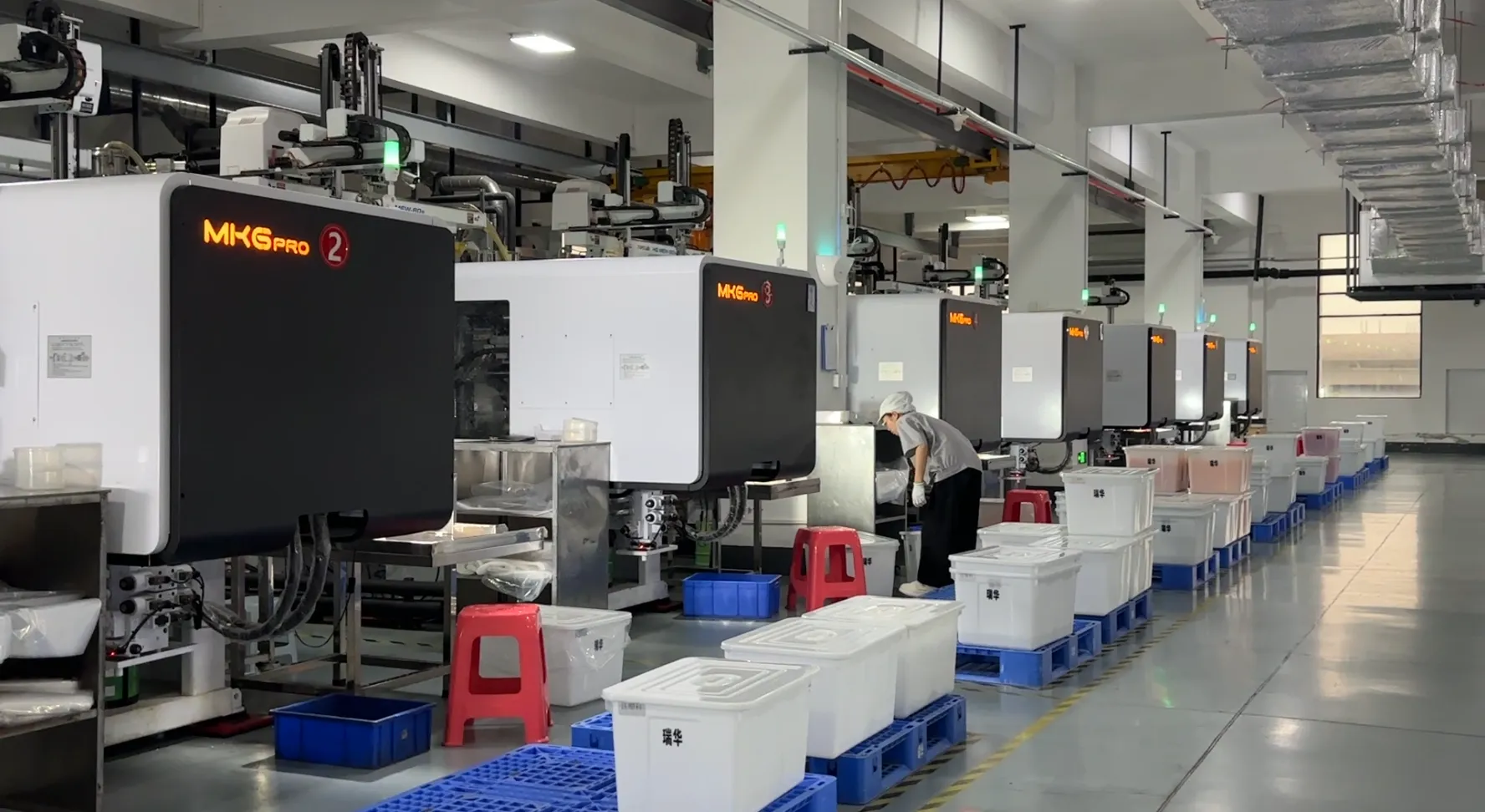
Resin choice is a molding constraint before it is a purchasing one. Resins that hold shape through a retort process are harder to mold than the ones that do not.
Compliance half. Food-contact suitability is a characteristic of the finished article and its documentation, not of the resin name. The route differs by market:
- In the United States, food-contact substances are handled through the FDA's Packaging & Food Contact Substances framework, and olefin polymers have a long-standing regulation at 21 CFR 177.1520 — which is the text your own regulatory team will want cited.
- In the European Union, the framework is Regulation (EC) No 1935/2004, with the plastic-specific requirements set by Regulation (EU) No 10/2011 and its positive list.
We hold ISO 9001:2015, HACCP, US FDA food-grade and EU 1935/2004 (TUV SUD) certificates, with GB 4806.7 and EU LFGB declared at product level on individual models. Two things are worth saying plainly. A certificate has a scope, and the scope is what matters — ask whether the declaration covers the finished part, the model you are buying, or just a resin grade. And if your market requires a specific declaration, ask for it by name and read the scope line; no honest supplier will do that reading for you.
Interface 5: changeover, stock and what a sample proves
A sample answers one question well: can this fitment be welded into this film. It does not answer the three questions that decide whether the line runs all week:
- can the feeder orient this cap at your line speed;
- does the weld stay consistent across a shift, at your dwell time, with your operators;
- does torque hold after the tenth changeover, not the first.
So ask for the sample and a small production run at your conditions, and measure the spread rather than the best piece. Torque across fifty caps and seal strength across a dozen packs will tell you more than any single passing sample. If you want the trial organized before you ask for it, the sample validation planner runs the same questions in order.
On the supply side, there are four commercial facts that change what a compatibility plan looks like:
- Stock and made-to-order are different products commercially. Four models are kept in stock — RD-001, RD-010, RD-013 and RD-014 — and stock models can be ordered at any quantity, which makes them the right choice for a trial. Custom colors are produced to your color reference and carry a substantial minimum, because changing color means cleaning the machine and changing material; after a tool has been opened for your part, there is no minimum at all. Mixing different models within one order is possible, which is what makes a multi-format trial affordable.
- Tooling has a sequence. A mold cost cannot be quoted before the 3D drawing is fixed, because the cost follows the geometry, the number of cavities and the steel. Once the drawing is fixed, a 3D-printed sample can be made for fit checks before any steel is cut, and tool production runs around 60 days. If your project has a date, the drawing is the critical path, not the quote.
- Inspection can be deepened on request. Machine-vision full inspection is available as an option rather than as a default on every order. If your validation plan requires it, say so when you request the quotation, not after the run.
- Certificates travel with the part. Ask for the declaration at the time of sampling, so the paperwork and the geometry are approved in the same review.

The drawing is the critical path. Every compatibility number you send ends up in this room before it ends up in steel.
The drawing comes first and the tool shop comes second, and they are the same project seen twice: the drawing decides the geometry, the tool shop decides whether that geometry can be held across a production run.
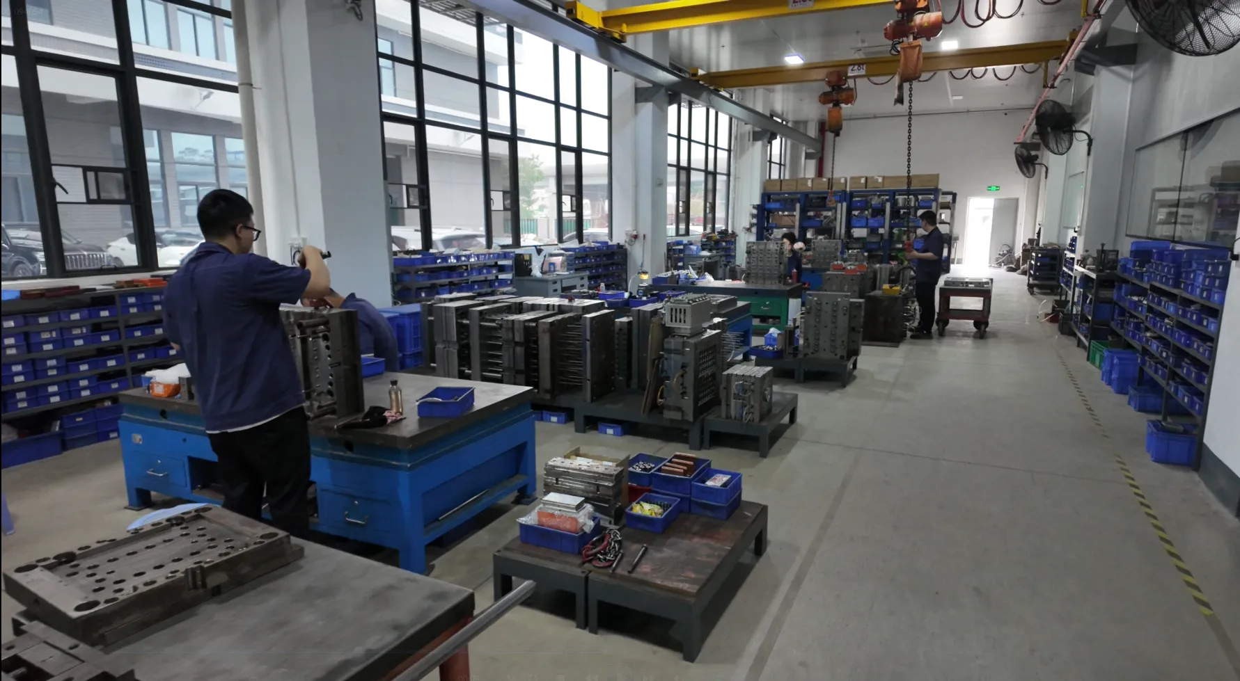
A custom fitment is a tooling project with its own calendar. The compatibility work happens before this shop gets involved.
Failure modes that show up in the first production week
The failures worth planning for are not exotic. They are the same five, in roughly this order, and each has a tell that points at an interface rather than at the part.
Symptom in week one | Most likely interface | What to check first |
|---|---|---|
Leaks appear after filling, not during | flange and weld | seal-zone contamination, and whether seal strength was ever measured at your dwell time |
Caps jam in the feeder, or arrive upside down | neck and cap profile | cap shape family against feeder tooling, not against the pouch |
Pouch top seal narrows at the spout | flange and weld | flange outer diameter against flat area across the pouch top |
Fill is slow, or product foams in the neck | bore | nozzle diameter and clearance, then product viscosity and particle size |
Torque readings spread after a changeover | neck and cap profile | capping head set for the previous cap diameter |
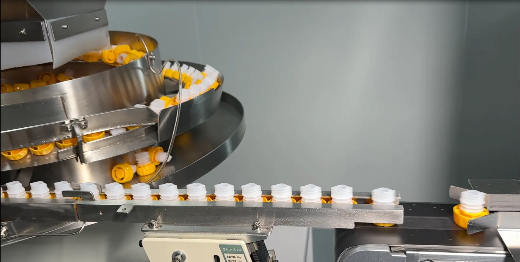
The feeder is where a trial either becomes a production process or does not. A full-inspection pass over every cap is available on request; ask for it at quotation time, not after the run.
Two of these deserve a word. A leak that appears after filling rather than during it is a seal-strength problem, and it usually means the weld was judged by eye or by a single passing sample — the pouch spout leaks after filling page takes that failure apart step by step. And a slow fill blamed on the fitment is, more often, a nozzle that was never measured.
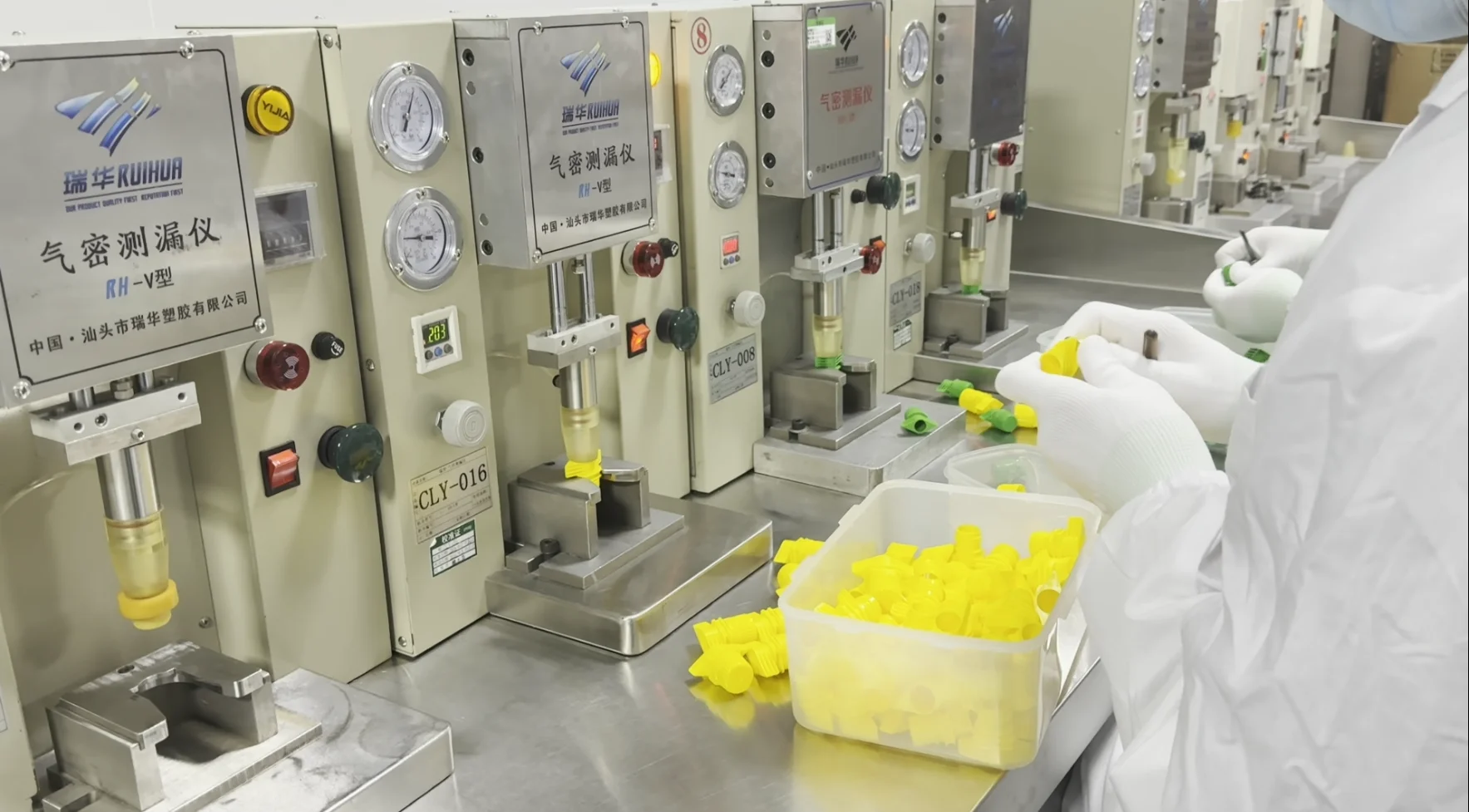
Seal integrity is a measured property, not an impression from the bench. Take the measurement before the run that matters.
The one-page sheet to send your supplier
Send this, and you will get a useful answer instead of a catalogue. Every line is something only your own team can measure.
Send: pouch format and finished dimensions · top seal width and jaw length · film structure and seal layer · fill route (through the spout or open top) · filler nozzle outer diameter · cap placement method and feeder type · capping torque target and head range · product viscosity and largest particle · process after sealing (retort, hot fill, ambient) · number of models you intend to run · target line speed.
Ask back, in writing: bore diameter and its tolerance for the model quoted · flange outer diameter and weld face width · neck height above the flange · weld temperature window, and whether the quoted figure is a welding figure or a process rating · cap material and the scope of its food-contact declaration · a seal made at your conditions with a seal-strength result · feeder-compatible cap samples · confirmation of what a trial run will be measured against.
If you want the same list in a form you can paste into an email, the spout cap specification sheet is the RFQ version of it.
Three things you can do today, in this order: measure your filler nozzle and your top seal width; photograph your cap feeder and write down its type; then send both to whoever is quoting the fitment, with the fill route and the process after sealing. Those four answers resolve most of the compatibility question before a single sample is made.
If you would rather hand the check over, send those same numbers to us and we will come back with the spout models that fit your line and a sample set you can run at your own conditions. Request a quote and a sample set, and mention any food-contact declaration your market requires — the paperwork can travel with the samples instead of arriving later.
Last reviewed: September 2026 by the Ruihua Technical Team. Dimensional and temperature figures quoted here are the ones published for our spout range; machine settings are specific to your line and must be confirmed with your machine builder.